44 SH-510-1
Consider closely with parallel
compounding
• For arrangement of oil separator,
oil cooler, suction and discharge
header and other design details
see Technical Information ST-600.
• Short distance between compres-
sor, oil separator and oil cooler
• Design variations with oil coolers
(see chapters 2.10, 9.4, 11.5, 11.6,
11.7 and figures 15 to 18):
- Individual arrangement
- common cooler (for maximum
number of compressors see tech-
nical description of the oil coolers
chapters 11.5 to 11.7 and BITZER
Software)
- arrangement in groups
essential when compounding
compressors with different suction
pressures (figure 17)
A prendre en compte pour
fonctionnement en parallèle
• Pour la disposition du séparateur
d'huile, du refroidisseur d'huile, des
collecteurs d'aspiration et de refoule-
ment ainsi que pour d'autres détails
d'exécution, voir Information technique
ST-600.
• Distance réduite entre compresseur,
séparateur d'huile et refroidisseur
d'huile
• Différentes exécutions avec des sépa-
rateurs d'huile (voir chapitres 2.10, 9,4,
11.5, 11.6, 11.7 et figures 15 à 18):
- adjonction individuelle
- refroidisseur commun (nombre max.
de compresseurs, voir description
technique chapitres 11.5 à 11.7 et
BITZER Software)
- adjonction par groupe
impératif lors de l'association de com-
presseurs avec différentes pressions
d'aspiration (figure 17)
Bei Parallelverbund unbedingt
beachten
• Anordnung von Ölabscheider, Öl-
kühler, Saug- und Druckkollektor
sowie weitere Ausführungsdetails
siehe Technische Information
ST-600.
• Geringer Abstand zwischen Ver-
dichter, Ölabscheider und Ölkühler
• Ausführungsvarianten mit Ölküh-
lern (siehe Kapitel 2.10, 9.4, 11.5,
11.6, 11.7 und Abb. 15 bis 18):
- individuelle Zuordnung
- gemeinsamer Kühler (max. Ver-
dichteranzahl siehe technische
Beschreibung der Ölkühler Kapitel
11.5 bis 11.7 sowie BITZER
Software)
- gruppenweise Zuordnung
zwingend bei Verbund von Ver-
dichtern mit unterschiedlichen
Saugdrücken (Abbildung 17)
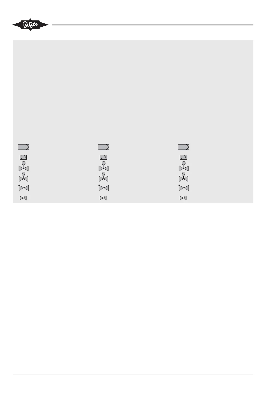
Legend
1 Motor-compressor unit
2 Standstill bypass (if required)
3 Oil separator with heater and oil
level switch
4 Condensing pressure
regulator (if required)
5 Water-cooled oil cooler
(only if required)
6 Condenser
7 Air-cooled oil cooler
8 Oil pump (only if required)
9 Mixing valve (if required, see
chapter 2.6)
Suction gas filter
Sight glass
Control valve
Solenoid valve
Check valve
Shut-off valve
Légende
1 Unit´r moteur-compresseur
2 Bipasse d'arrêt (si nécessaire)
3 Séparateur d'huile avec résistance
et contrôleur de niveau d'huile
4 Régulateur de pression de conden-
sation (si nécessaire)
5 Refroidisseur d'huile à eau
(seulement si nécessaire)
6 Condenseur
7 Refroidisseur d'huile à air
8 Pompe à huile (si nécessaire)
9 Vanne de mélange (si nécessaire,
voir chapitre 2.6)
Filtre du gaz d'aspiration
Voyant
Vanne de régulation
Vanne magnétique
Clapet de retenue
Vanne d'arrêt
Legende
1 Motor-Verdichter-Einheit
2 Stillstands-Bypass (bei Bedarf)
3 Ölabscheider mit Heizung und
Ölniveauwächter
4 Verflüssigungsdruck-Regler
(nur bei Bedarf)
5 Wassergekühlter Ölkühler
(nur bei Bedarf)
6 Verflüssiger
7 Luftgekühlter Ölkühler
8 Ölpumpe (nur bei Bedarf)
9 Mischventil (bei Bedarf, siehe
Kapitel 2.6)
Sauggasfilter
Schauglas
Regelventil
Magnetventil
Rückschlagventil
Absperrventil