The B&K Precision MDL Series is a multi-channel programmable DC electronic load system designed for testing various power sources, including multi-output DC power supplies, batteries, fuel cells, and photovoltaic arrays. This system offers extensive programming and remote control capabilities, making it a versatile solution for diverse design requirements.
Function Description
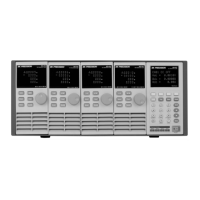
The MDL Series consists of mainframes (MDL001 and MDL002 extension) and user-selectable modules (MDL200, MDL252, MDL302, MDL305, MDL400, MDL505, and MDL600). The MDL001 mainframe can accommodate up to four modules, supporting a total of 8 channels. With the MDL002 mainframe extension, the system expands to support four additional module slots, allowing for a maximum of 16 channels. The electronic load can be operated via the front panel keypad and rotary knob or controlled remotely through USB, RS-232, LAN, or GPIB interfaces.
The device offers five distinct operating modes:
- Constant Current (CC) mode: The electronic load sinks a programmed current regardless of the input voltage.
- Constant Voltage (CV) mode: The electronic load sinks enough current to control the source voltage to a programmed value.
- Constant Resistance (CR) mode: The electronic load acts as a constant resistance, linearly changing the current according to the input voltage.
- Constant Power (CW) mode: The electronic load consumes a constant power, where input current decreases as input voltage increases, maintaining a constant P = V*I.
- Constant Impedance (CZ) mode: Utilizes an A/D converter and DSP calculation to simulate the transient current wave of tested components.
Important Technical Specifications
- Input Voltage:
- MDL200, MDL252, MDL302, MDL400, MDL600: 0-80 V
- MDL305, MDL505: 0-500 V
- Input Current:
- MDL200: Low 0-4 A, High 0-40 A
- MDL252: Low 0-3 A, High 0-20 A
- MDL302: Low 0-4.5 A, High 0-45 A
- MDL305: Low 0-3 A, High 0-20 A
- MDL400: Low 0-6 A, High 0-60 A
- MDL505: Low 0-3 A, High 0-30 A
- MDL600: Low 0-12 A, High 0-120 A
- Input Power:
- MDL200: 200 W
- MDL252: 250 W
- MDL302: 300 W
- MDL305: 300 W
- MDL400: 400 W
- MDL505: 500 W
- MDL600: 600 W
- Channels: MDL200, MDL305, MDL400, MDL505, MDL600 (1 channel); MDL252, MDL302 (2 channels).
- Minimum Operating Voltage: Varies by module and current range (e.g., 0.10 V at 4 A for MDL200 Low, 1 V at 40 A for MDL200 High).
CV Mode:
- Range: Low 0-18 V (all modules), High 0-80 V (MDL200, MDL252, MDL302, MDL400, MDL600), 0-500 V (MDL305, MDL505).
- Resolution: Low 1 mV, High 10 mV.
- Accuracy: ±(0.05%+0.02% FS) for Low, ±(0.05%+0.025% FS) for High.
CC Mode:
- Range: Varies by module, matching input current ranges.
- Resolution: Low 0.01 mA (most modules), High 0.1 mA (most modules).
- Accuracy: ±(0.05%+0.05% FS) (most modules), ±(0.05%+0.1% FS) or ±(0.1%+0.1% FS) for MDL600.
CR Mode:
- Range: 0.05 Ω-10 Ω (most modules), 0.25 Ω-10 Ω (MDL305), 10 Ω-7.5 kΩ (all modules).
- Resolution: 16 bit.
- Accuracy: 0.01%+0.08 S (Low), 0.01%+0.0008 S (High).
CW Mode:
- Range: Matches input power ranges.
- Resolution: 10 mW.
- Accuracy: ±(0.2%+0.2% FS).
Transient Mode (CC mode):
- T1&T2: 20us-3600s/Res:5us-10ms.
- Accuracy: 5us+100ppm.
- Slew Rate: 0.0001-0.25 A/us (Low), 0.001-2.5 A/us (High), with variations across modules.
Protection Range (typical):
- OPP: 200 W (MDL200) to 600 W (MDL600).
- OCP: Low 3.3 A (MDL252, MDL305, MDL505) to 13.2 A (MDL600), High 20 A (MDL252, MDL305) to 132 A (MDL600).
- OVP: 82 V (most modules), 510 V (MDL305, MDL505).
- OTP: 85°C.
General (typical):
- Short Circuit Current (CC): Low 3 A (MDL252, MDL305, MDL505) to 12 A (MDL600), High 20 A (MDL252, MDL305) to 120 A (MDL600).
- Short Circuit Voltage (CV): 0 V.
- Short Circuit Resistance (CR): 15 mΩ (MDL600) to 220 mΩ (MDL305).
- Input Terminal Impedance: 300 kΩ (most modules), 1 MΩ (MDL305, MDL505).
Usage Features
- Removable Modules: Facilitates easy system flexibility and configuration.
- Bright VFD Display: Provides clear information for both the mainframe and individual modules.
- Parallel Mode: Allows identical modules to operate in parallel for high current applications, supporting up to 2400 W (4800 W with mainframe extension).
- Synchronous Load On/Off: Enables simultaneous control of multiple channels.
- High Resolution Metering: 16-bit voltage and current metering offers 0.1 mV and 0.01 mA resolution.
- Transient Mode: Supports transient operations up to 25 kHz, including continuous, pulse, and toggle modes, with user-programmable slew rates, load levels, and durations.
- List Mode: Allows for complex sequences of input changes with a minimum 20 µs step width and up to 84 user-programmable steps.
- Adjustable Slew Rate: Available in CC mode for controlled transitions between load settings.
- Automatic Test Function: Supports up to 10 program files, each with 10 steps, and allows for setting Pass/Fail criteria, suitable for production environments.
- Memory Areas: 101 memory areas to save and recall setting parameters (Group 0 for power-up, Groups 1-100 for automatic testing).
- Analog Current Control and Monitoring: External analog control via pin 7 and pin 8 for current setting in CC mode (0-10 V signal). Current monitoring output (0-10 V analog signal) for external display.
- Remote Sensing: Compensates for voltage drops in long leads, providing better measurement accuracy.
- External Trigger Connections: Five trigger modes (Manual, External, Hold, Bus, Timer) for synchronized operations.
- External ON/OFF Control: TTL level pulse input (pin 3) to toggle load inputs ON/OFF, and TTL level signal output (pin 4) to indicate ON/OFF state.
- Von Operation: Controls the voltage turn-on state for the electronic load, protecting the DUT when its voltage drops below a specified level.
- Short Operation: Simulates a short circuit at the input for testing purposes.
- Communication Interfaces: Standard LAN, GPIB, USBTMC compliant USB, and RS-232 interfaces with SCPI protocol support for remote control.
Maintenance Features
- Inspection: Upon receipt, inspect for transit damage and notify the distributor if any is found.
- Cleaning: Use a dry cloth or one slightly dampened with water to clean external case parts. Disconnect power cord before cleaning. Do not attempt internal cleaning.
- Fuse Replacement: If a fuse is blown, replace it with the appropriate specification (T5A, 250V for 110VAC or T2.5A, 250V for 220VAC).
- Calibration: Recommended calibration period is once per year.
- Environmental Conditions: Intended for indoor use in pollution degree 2 environments, with an operating temperature range of 0 to 40 °C and storage temperature of -10 to 60 °C. Relative humidity should be ≤ 95%.
- Air Circulation: Ensure adequate space (minimum 2 inches from top, 3 inches from front and back) for proper air circulation, especially when rack-mounted or used on a bench. Avoid blocking fan exhaust.
- Safety Precautions: Adhere to all safety precautions, including proper grounding, avoiding explosive atmospheres, and not servicing or adjusting alone. Only qualified service personnel should remove covers or replace components.