EasyManua.ls Logo

BK Precision MDL001 - Page 78

BK Precision MDL001
82 pages
Print Icon
To Next Page IconTo Next Page
To Previous Page IconTo Previous Page
Loading...
78
Notes:
1)
MDL252: User can allocate up to 250 W to either channel up to 300 W total (e.g. 50 W/250 W, 250 W/50 W, 150 W/150 W).
2)
Fast pulse trains with large transitions may not be achievable.
3)
The slew rate specifications are not warranted but are descriptions of typical performance. The actual transition time is
defined as the time for the input to change from 10% to 90%, or vice versa, of the programmed current values. In case of
very large load changes, e.g. from no load to full load, the actual transition time will be larger than the expected time. The
load will automatically adjust the slew rate to fit within the range (high or low) that is closest to the programmed value.
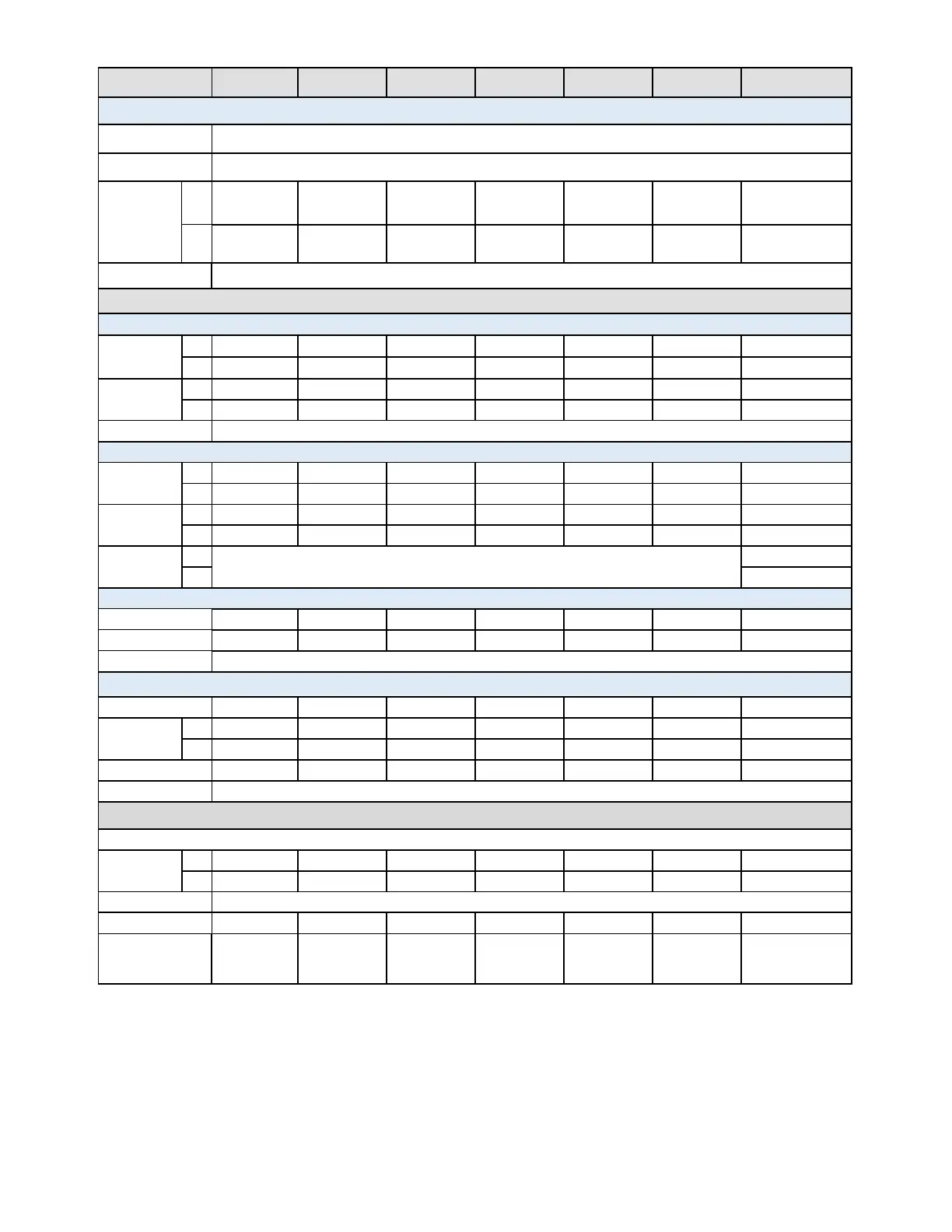
Model MDL200 MDL252 MDL302 MDL305 MDL400 MDL505 MDL600
Transient Mode (CC mode)
T1&T2
2
20us-3600s/Res:5us-10ms
Accuracy 5us+100ppm
Slew Rate
3
Low
0.0001-0.25
A/us
0.0001-0.2
A/us
0.0001-0.25
A/us
0.0001-0.1
A/us
0.0001-0.25
A/us
0.0001-0.1
A/us
0.0001-0.25
A/us
High
0.001-2.5
A/us
0.001-2 A/us
0.001-2.5
A/us
0.001-1 A/us
0.001-2.5
A/us
0.001-1 A/us
0.001-2.5 A/us
Accuracy within 40% of programmed value
Measurement
Readback voltage
Range
Low
0-18 V
0-18 V
0-18 V
0-18 V
0-18 V
0-18 V
0-18 V
High
0-80 V
0-80 V
0-80 V
0-500 V
0-80 V
0-500 V
0-80 V
Resolution
Low
0.1 mV
0.1 mV
0.1 mV
1 mV
0.1 mV
1 mV
0.1 mV
High
1 mV
1 mV
1 mV
10 mV
1 mV
10 mV
1 mV
Accuracy
±(0.025%+0.025%FS)
Readback current
Range
Low
0-4 A
0-3 A
0-4.5 A
0-3 A
0-6 A
0-3 A
0-12 A
High
0-40 A
0-20 A
0-45 A
0-20 A
0-60 A
0-30 A
0-120 A
Resolution
Low
0.01 mA
0.01 mA
0.01 mA
0.01 mA
0.1 mA
0.01 mA
0.1 mA
High
0.1 mA
0.1 mA
0.1 mA
0.1 mA
1 mA
0.1 mA
1 mA
Accuracy
Low
±(0.05%+0.05%FS)
±(0.05%+0.1%FS)
High
±(0.1%+0.1%FS)
Readback power
Range
200 W
250 W
300 W
300 W
400 W
500 W
600 W
Resolution
10 mW
10 mW
10 mW
10 mW
10 mW
10 mW
10 mW
Accuracy
±(0.2%+0.2%FS)
Protection Range (typical)
OPP
200 W
250 W
310 W
300 W
400 W
500 W
600 W
OCP
Low
4.4 A
3.3 A
5 A
3.3 A
6.6 A
3.3 A
13.2 A
High
44 A
22 A
50 A
22 A
66 A
33 A
132 A
OVP
82 V
82 V
82 V
510 V
82 V
510 V
82 V
OTP
85
General (typical)
Short Circuit
Current (CC)
Low
4 A
3 A
5 A
3 A
6 A
3 A
12 A
High
40 A
30 A
50 A
20 A
60 A
30 A
120 A
Voltage (CV)
0 V
Resistance (CR)
25 mΩ
50
30
220 mΩ
25 mΩ
180 mΩ
15
Input Terminal
Impedance
300 kΩ 300 kΩ 300 kΩ 1 MΩ 300 kΩ 1 MΩ 300 kΩ

Table of Contents