66
Electrical System
Procedure For Disconnecting A Shore
Connection
Turn the circuit breaker on the dockside outlet to
the OFF position. Disconnect the cable from the
dockside outlet and close the outlet cap. Discon-
nect the cable from the inlet plug and close the
cap. Store cable.
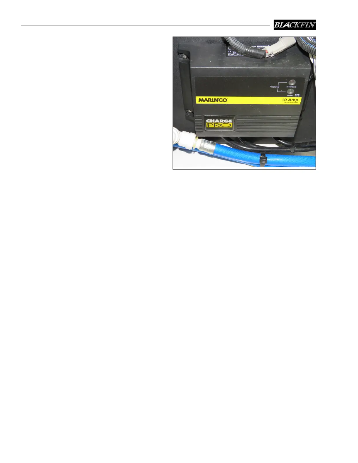
Battery Charger (Optional)
The battery charger is mounted near the batter-
ies in the aft systems compartment. AC electrical
current is supplied directly to the battery charger
by the shore power cable. The charger automati-
cally charges and maintains the engine and house
batteries simultaneously when activated. It is
equipped with LED lights to indicate the state of
charge for each battery.
The charge to the batteries can be monitored by
using the volt meter in the engine gauge cluster
or the LED lights on the charger. To monitor the
batteries with the volt meter in the engine gauge
cluster, activate the charger and turn the engine
battery switch to the 1 & 2 position. Turn the igni-
tion switch for the engine to the ON position (DO
NOT START THE ENGINE) and read the voltage
on the volt meter.
If the batteries are in good condition and charging
properly, the volt meter will indicate between 12
and 14.5 volts. If the reading is below 12 volts,
then the batteries are not accepting a charge or
the charger is not working properly. Always turn
the ignition switch o immediately after monitor-
ing is complete when using the voltmeter in the
engine gauge cluster.
The wires that supply DC charging current to the
batteries are protected by an internal fuse in the
battery charger and external fuses, one for each
battery output wire, located near each battery.
The external fuses protect the DC charging circuit
from the batteries to the charger. The internal
fuses in the charger protect the DC charging circuit
from the charger to the batteries. See the battery
charger manual for more information.
6.8 Bonding System
Your boat is equipped with a bonding system that
interconnects the underwater metal hardware and
the engine to ensure that they are of the same
electrical potential. Sacricial anodes of the size
and type recommended by the engine manufac-
turer are attached to the outboard motor. There
could also be sacricial anodes on each trim tab
plane that are isolated from the boat bonding
system to protect each tab plane assembly if the
boat is to kept in saltwater.
Anodes deteriorate before other metals, thereby
protecting the underwater metals from galvanic
corrosion or stray electrical current. Since the
anodes are sacricial, it is important to monitor
them and replace them when they have deterio-
rated to 50-75% of their original size.
The bonding system is connected to the engine
and battery DC ground. If your boat is equipped
with the optional battery charger, the earth ground
wire for the AC electrical system is also connected
to the bonding system. It provides a path to the
safety earth ground in the event of a fault in the
shore earth ground connection.
Battery Charger


 To Next Page