3. The lift
9
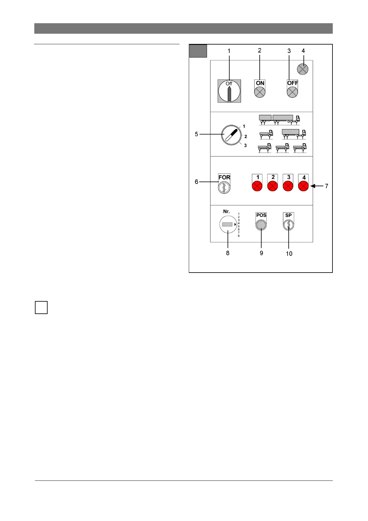
3.4 Control cabinet
Illustration 11: Controls on control cabinet
1 Main switch, emergency stop
2 Controls On
Turns the main contactor on. The control panels
are now activated.
3 Controls Off
Turns the main contactor off. The control panels
are now deactivated.
4 Buzzer
Acoustic alarm during lowering the lift below 500
mm (foot protection).
5 Lift allocation switch (optional)
Lifts with 4, 5 or 6 lifting cylinders can be divided
into individual workplaces.
● A control panel is available for each work-
place.
● The individual control panels are activated
corresponding to the lift allocation.
6 FOR key switch
Manual adjustment of the vehicle position.
● Automatic controls are deactivated.
● Current lift allocation is canceled.
● Control panel 1 is activated.
● Control commands Up and Down apply
to activated lifting cylinder.
For safety reasons, a second operator must
be called in. This person must permanently
activate FOR switch and monitor the operator.
7 Fault report indicators L1 ... L4
15 fault reports are allocated to the 4 indicators,
depending on On/Off combination ( chapter
7).
Distance between axles preset “AAV”, optional
( chapter 5.14).
8 Rotary switch for 9 memory presets
The necessary lifting cylinder positions for fre-
quently used vehicles can be stored.
9 POS button
The lifting cylinders move to the selected posi-
tion.
10 SP key switch
The current lifting cylinder position is pro-
grammed for the set memory preset (position
number).