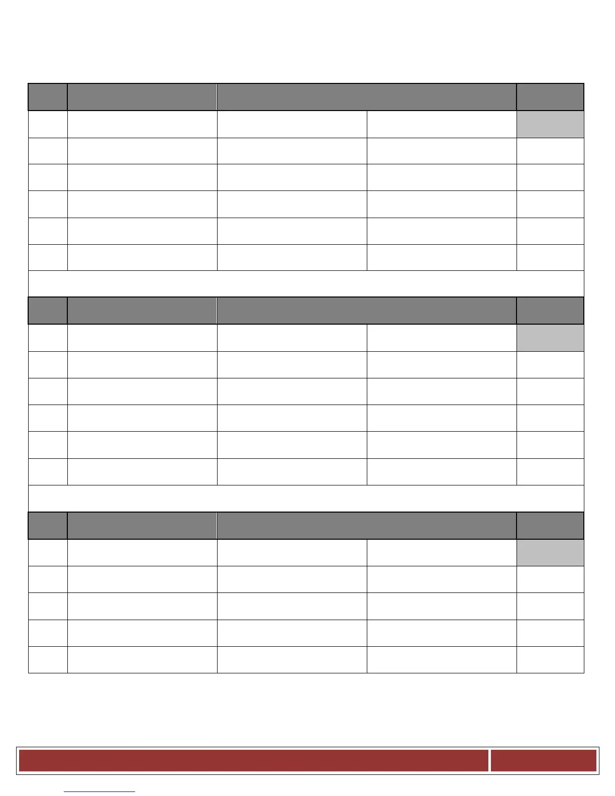
BCX14E - Trouble shooting test points
~ (Bottom) DC Voltage Power Supply Test Points ~
# Component
Black lead Red Lead
AC + DC
1
DC Power Supply
Power supply (N) Power supply (L)
115 VAC
2
DC Power Supply
Power supply (-V) Power supply (+V)
24 VDC
3
BCX2 (Logic Board)
J1 Connector (J1-1) BK-
24vdc_Rtn
J1 Connector (J1-4) RD-
+24vdc_H
24 VDC
4
BCX2 (Logic Board)
DC Power Supply
J1 Connector (J1-1) BK-
24vdc_Rtn
terminal at power supply
24 VDC
5
DC Power Supply
(-
terminal at power supply
J1 Connector (J1-4) RD-
+24vdc_H
24 VDC
6
(IFB) Relay Board
J7 Connector (J7-2) Black J7 Connector (J7-1) Red
24 VDC
~(Top) Heat DC Voltage Power Supply Test Points 2 ~
# Components Testing
Black lead Red Lead
Voltage AC
+ DC
1
DC Power Supply
Power supply (N) Power supply (L)
115 VAC
2
DC Power Supply
Power supply (-V) Black Power supply (+V) Red
24 VDC
3
Hot Air Contactor
Contactor Coil (A2) Black Wire
Boiler High limit ( Red Wire )
24 VDC
4
Hot Air Contactor
Contactor Coil (A2) Black Wire
Boiler High limit ( Yellow Wire )
24 VDC
5
Hot Air Contactor
Contactor Coil (A2) Black Wire
Hot Air High limit ( Red Wire )
24 VDC
6
Hot Air Contactor
Contactor Coil (A2) Black Wire
Hot Air High limit ( Orange Wire )
24 VDC
~ Cool Down Operation at Low Speed ~
# Components Testing
Black lead Red Lead
Voltage AC
+ DC
1
Motor Speed Inverter
( N ) ( L )
115 VAC
2
BCX2 (Logic Board)
Mode SW Terminal #4
J1 Connector J1-4
24 VDC
3
BCX2 (Logic Board)
Inverter Terminal #CW2
J1 Connector J1-4
24 VDC
4
BCX2 (Logic Board)
( IFB ) Connector J3 (J3-7) J1 Connector J1-4
24 VDC
5
BCX2 (Logic Board)
( Inverter ) Terminal #2 & #3 ( Inverter ) Connector J1-4
24 VDC