9
Utility Connection
Installation
ELECTRICAL CONNECTION
NOTE: Electrical connection must be performed by a
qualied installer only.
NOTE: The electrical connection must comply with Na-
tional and Local codes.
A strain relief for the supply cord is required. The installer
must provide a supply cord bushing that meets all Local
and National Installation Standards.
If using a exible cord, it needs to be type H07RN-F.
For Gas Models:
NOTE: Gas models have a phase sensitive burner con-
trol unit. If the phase and neutral are switched the
control locks out.
Connect phase + neutral + ground.
For Electric Models:
Connect the oven to a separate group with rigid connec-
tion and circuit breaker. The circuit breaker should discon-
nect all poles, including neutral with a contact separation
of at least 3 mm.
For 1 Phase - Connect phase + neutral + ground.
For 3 Phase -Connect L1 + L2 + L3 + neutral + ground.
INITIAL STARTUP
1. Set the THERMOSTAT to 260°C and operate for 2
hours prior to loading product. This procedure pro-
duces smoke.
2. Clean the oven after the initial burn-in process. See
page 13 for proper cleaning instructions.
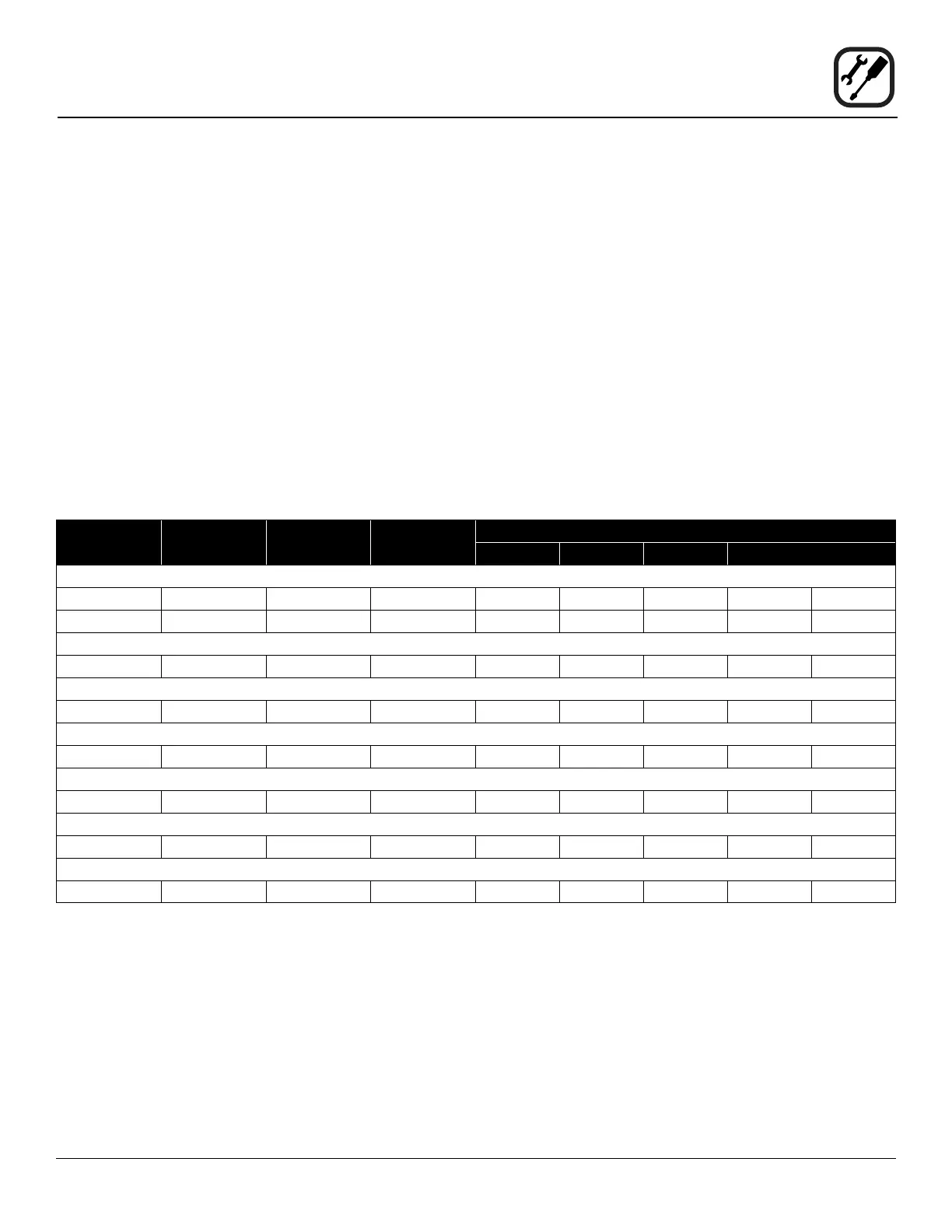
KW/Section Voltage Phase
Frequency
(Hz)
Max Load
L1 L2 L3 N mm
2
CTB/CTBR
5,6 400 3N 50 9 8 8 1 5 x 2.5
8,0 400 3N 50 13 11 11 2 5 x 2.5
Mark V-100
11,0 400 3N 50 18 15 15 3 5 x 2.5
Zephaire-200-E
11,0 400 3N 50 18 15 15 3 5 x 2.5
Zephaire-100G-ES
0,7 230 1N 50 3 - - 3 3 x 1.5
Zephaire-200G-ES
0,7 230 1N 50 3 - - 3 3 x 1.5
DFG-100-ES
0,7 230 1N 50 3 - - 3 3 x 1.5
DFG-200-ES
0,7 230 1N 50 3 - - 3 3 x 1.5