179
Task Procedures Illustrations
Task Procedures Illustrations
AT6020
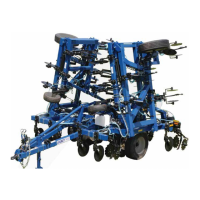
Generic Photo
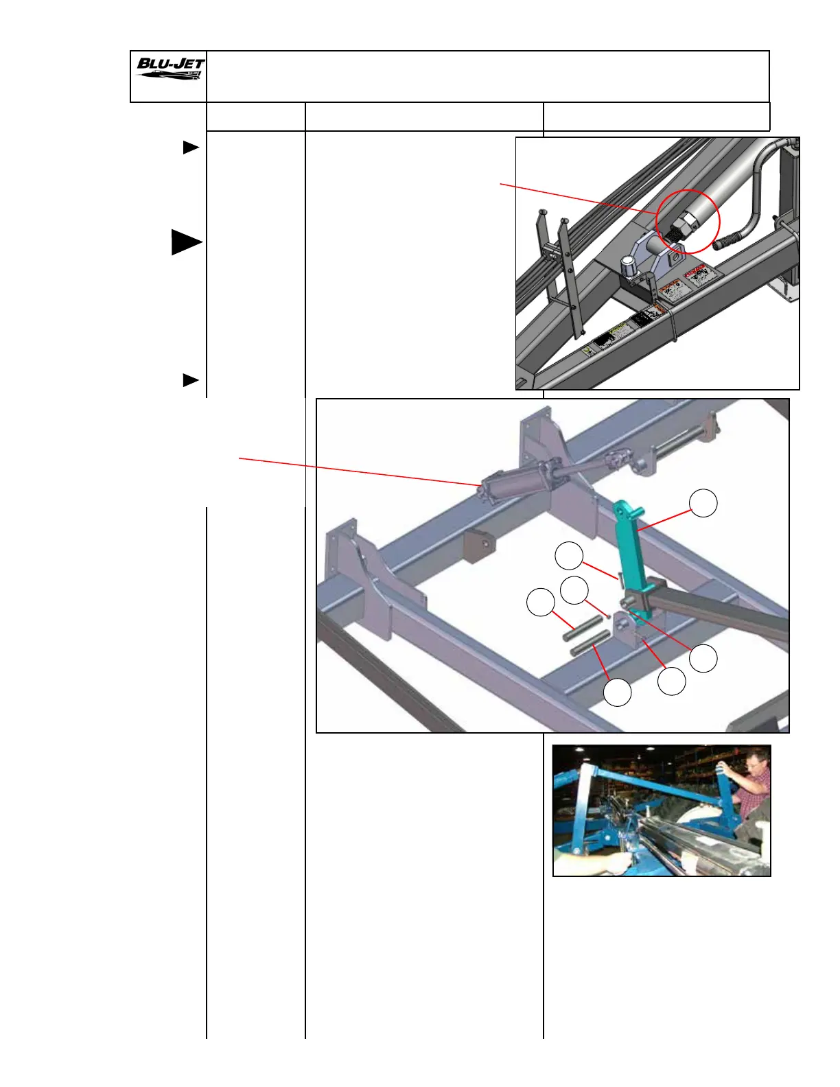
1. Loosen turnbuckle nut to
lower the tongue cylinder
linkage into position.
Mounting
tongue
cylinder
linkage
NOTE:
Left-hand
and
right-hand
as viewed
from the
rear
Tongue Linkage Assembly
a
b
d
c
c
b
2. Mount (a) (AM6182) tongue
cylinder arm linkage to main
frame weldment with (b)
(BM3465) 1-1/4” x 7-3/4” pin
with 13/32” hole.
Secure pin with (c) (BP3096)
3/8” x 2-1/2” hex cap screw
and (d) (BP3003) 3/8” hex
lock nut.
3. Raise tongue cylinder
linkage and connect to arm
with (b) (BM3465) 1-1/4” x
7-3/4” pin with 13/32” hole.
Secure pin with (c) (BP3096)
3/8” x 2-1/2” hex cap screw
and (d) (BP3003) 3/8”
hex lock nut.
(DP4483) 3-1/4” x 12”
Rephasing Cylinder
Expandable Model
or
(DP4484) 3-1/2” x 12”
Economy Model
d