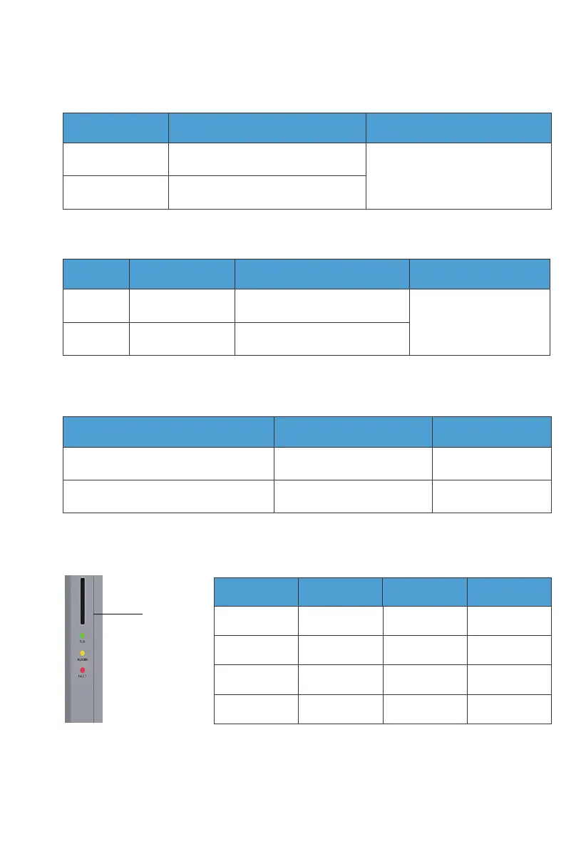
3.4 LED Indicator
Fig. 3-2
Indicator
Situation
No alarm and
fault
ON
ON ON
ON
/
/
//
/
/ ON
ON
Alarm
Fault
Alarm and fault
Run Alarm Fault
3.3.5. LINK PORT 1 & LINK PORT 2
Table 3-6
Table 3-9
Interface Function Note
Refer to Fig. 6-7 for details.
Link Port 1
Link Port 2
Connect the IoT controller
Connect the battery pack
3.3.7. COM Port
Table 3-8
RS485 Meter Communication Port Function Wiring
A (1) (L)
B (2) (N)
A: RS485 differential signal +
B: RS485 differential signal -
Connect to meter A2
Connect to meter B2
3.3.6. CT Port
Table 3-7
PIN Definition Description Note
Connect to the Phase
L CT in the grid.
L
N
CT-L1+ (Red)
CT-L1- (Black)
CT output positive terminal
CT output negative terminal
JUST POWER ON26