EasyManua.ls Logo

BLUM AVENTOS HL

BLUM AVENTOS HL
8 pages
To Next Page IconTo Next Page
Loading...
AVENTOS HL
Subject to technical modifications without notice. © 2015
1
Cover set
Right and left cover plate
Non-handed cover caps
Part no.
Cover set
20L8000.N1
Lift mechanism set
Lift mechanism (qty 2)
#7 x 35 mm (1-3/8") wood screw (qty 10)
20L2100.N5
20L2300.N5
20L2500.N5
20L2700.N5
20L2900.N5
Arm assembly set
Right and left arm assembly
Stabilizer rod cover cap (qty 2)
Cabinet height Part no.
300 (11-13 /16 ") 349 (13-3/4")
20L3200.06
350 (13-13/16") 399 (15-13/16")
20L3500.06
400 (15-3/4") 550 (21-5/8")
20L3800.06
450 (17-11/16" ) 580 (22-13/16")
20L3900.06
Wood/wide aluminum door hardware set
Part no.
Wood/wide aluminum hardware set
20S4200
Installation screw for wood doors
606N or 606P
Installation screw for aluminum
7072A
Mounting plate with bracket set
Part no.
Plate with bracket set
20S4F01
Wood/wide aluminum
hardware set
Oval stabilizer rod
Oval stabilizer rod
Aluminum rod length 1061 (41-3/4"), cut to size
Length
=
interior cabinet opening minus 129 (4-13/16")
Part no.
Oval stabilizer rod
20Q1061UA
NOTE: For cabinets wider than 48" two stabilizer rods and stabilizer rod connector set required
Arm assembly mounting plate (qty 2) Mounting plate with bracket (left
and right)
For large overlay five-piece doors

Other manuals for BLUM AVENTOS HL

Question and Answer IconNeed help?

Do you have a question about the BLUM AVENTOS HL and is the answer not in the manual?

BLUM AVENTOS HL Specifications

General IconGeneral
CategoryLift system
Cabinet width rangeUp to 1800 mm
BLUMOTIONYes
SERVO-DRIVEOptional
ApplicationLift system for wall cabinets
Cabinet height range300 mm to 580 mm
Motion technologyBLUMOTION
MaterialSteel
Adjustment3-dimensional adjustment
Opening Angle StopOptional
MountingScrew-on system

Summary

Locating Pin Locations and Minimum Depth

Attaching the Lift Mechanism

Mechanism Alignment and Attachment

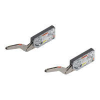
Guides on aligning and attaching the lift mechanism with screws.

Attaching the Arm Assembly

Arm Assembly Connection

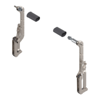
Details connecting right/left arm assemblies to the lift mechanism.

Attaching the Stabilizer Rod

Attaching the Mounting Plates

Attaching the Door

Door to Arm Assembly Connection

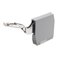
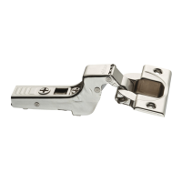
Instructions for attaching the door to the arm assembly via CLIP mechanism.

Adjusting Lift Mechanism Tension

Tension Adjustment Procedure

Use a screw gun with a POZI driver bit to adjust lift mechanism tension.

Adjusting the Door

Cam Adjustment for Door Alignment

Use a POZI screwdriver for three-dimensional adjustments to the door.

Removing the Door

Door Disengagement from CLIP

Support door, push tab to disengage CLIP mechanisms on arm assemblies.

Lifting Door Off Mounting Plates

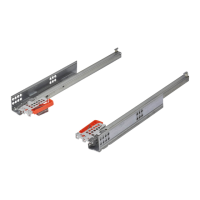
Lift the door off the mounting plates after disengagement.

Removing Covers

Removing the Stabilizer Rod

Stabilizer Rod Cover Caps and Rod

Pull back cover caps and remove the stabilizer rod from the arm assembly.

Removing the Arm Assembly

Arm Assembly Disengagement

Use a screwdriver to disengage both arm assemblies from the mechanism.

Related product manuals