MD8 MAIN FRAME INSTALLATION
15
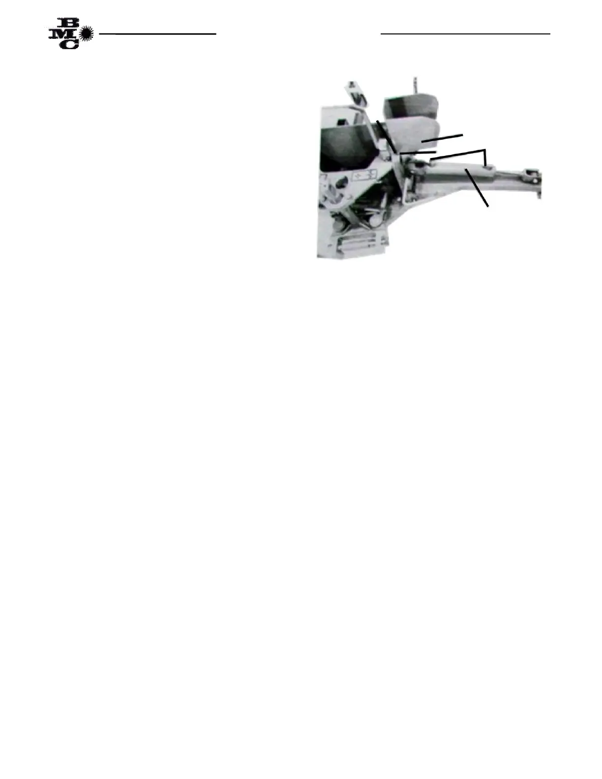
(7) Attach base end of one (1) each stabilizer cylinder
(Item 9) to left side of main frame cylinder anchor lug,
located in the center and just above the base end of the
stabilizer arm, using one each cylinder pin (Item 10)
and two each 3/16” x 1 ½” cotter pins (Item 11) as
shown in Fig. 5.
(8) Attach the rod end of the stabilizer cylinder to the
anchor lug, located in the center of the stabilizer arm
near the stabilizer foot, using one each cylinder pin
(Item 10) and two each 3/16” x 1 ½” cotter pins (Item
11) as shown in Fig. 5.
(9) Attach the right side stabilizer cylinder by
repeating steps 7 and 8.
(10) Attach the right stabilizer guard (Item 7) over the
mounting receptacle, located on the upper portion of
the main frame side plate, aligning the two holes in the
stabilizer guard with the mounting receptacle and
inserting the guard pin (Item 8) through the guard and
receptacle. Secure the pin with two each 1/8” x 1”
cotter pins (Item 12) as shown in Fig. 6.
Fig. 6
(11) Attach the left stabilizer guard by repeating
step 11.
(12) Install one each of the SAE 6 O-Ring to JIC 6
Flare Straight adaptor fittings (Item 1 in box parts list,
page 5) in both ports of the right and left stabilizer
cylinders (four (4) required) as shown in Fig. 6.
NOTE: It is very important to check the torque on the eight 5/8” x 2” machine bolts retaining the mainframe to the
mounting frame top plate after eight (8) hours of operation and every 40 hours of operation thereafter. It is
acceptable, once operation of backhoe and mounting frame adaptation to tractor has proved satisfactory, to weld the
mainframe to the mounting kit.
1
7
8
9
12