Detailed assembly instructions Detailed assembly instructions
38
39
Speedmachine Owners Manual
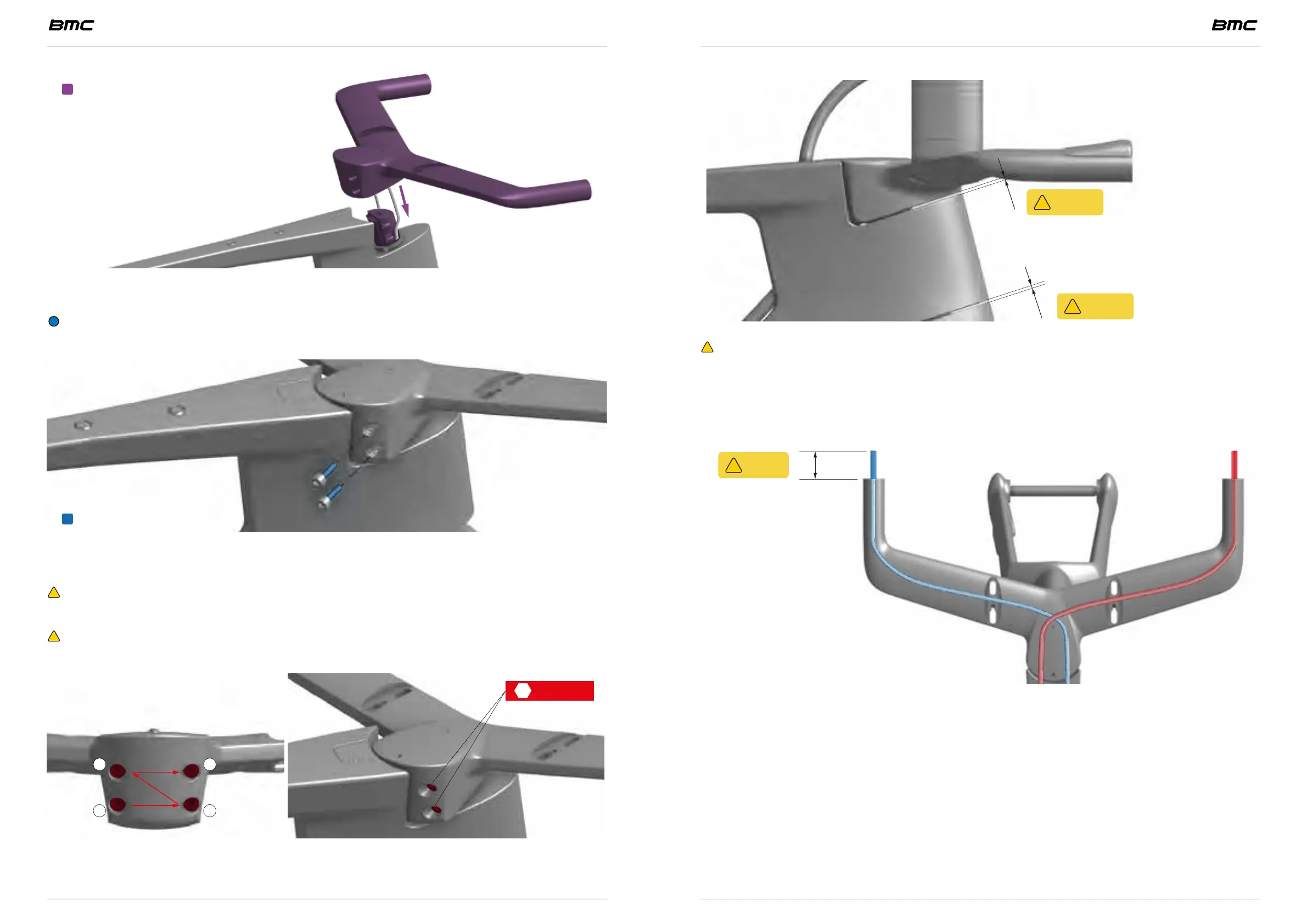
Align and slide over
• Install the base bar onto the headset sleeve.
INFORMATION: It will help to pull the brakes hoses from the base bar grip to help
push the base bar onto the headset sleeve.
Thread locker
• Turn the bar on one side and install 2 of the M5x16.5. Tighten lightly.
• Turn the bar to the other side and install the other 2 M5x16.5 bolts
WARNING: Bolt on the bolts completely in order to avoid their head to damage the
frame paint when turning the bar.
WARNING: If necessary, replace the original thread locker compound by a fresh
coat of LOCTITE 243.
4 5 Nm
1 2
3 4
Repeat sequence 2 times
• Follow the tightening sequence as illustrated: lower left, lower right, upper left, upper
right and repeat 2 times. Tighten the 4 bolts to 5 Nm using a 4 hex wrench.
•
0.5mm
mini
!
0.5mm
mini
!
WARNING: Once handlebar bolts are tighten to specifications, control the space
required betweeen the base bar and the top of the head tube as well as between the
head tube and the fork crown.
The clearance must be of 0.5mm minimum.
30mm
mini
!
• Cut the brake lines leaving at least 30mm of hose. This will make the lever installation
easier and it will help you when removing the base bar for transportation.
• Install the brake levers following the manufacturer’s instructions.