BMG LABTECH Omega Operating Manual
2014-05-16 0415B0001G 13/29
If the instrument needs to be moved to a new location, the plate carrier should be in the locked position
otherwise the transport system could be damaged.
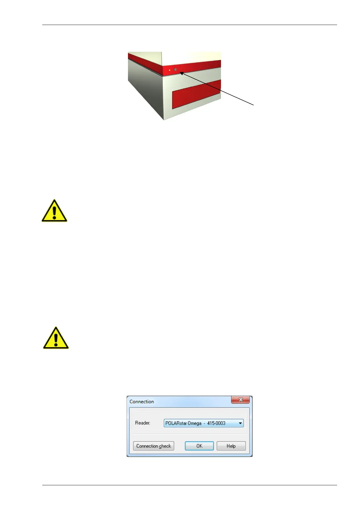
Figure 2: Plate In / Plate Out button
Press and hold the plate in / plate out button for 3 seconds, hereafter the plate carrier will automatically move
to its lock position. Once the reader is switched off, the transport pin can be moved down and turned
clockwise. The transport pin must be screwed until it tightens. Please tighten it firmly with your fingers. Don’t
use any tools.
The transport system is locked when the transport lock is in its down position and firmly tightened.
3.2 Software Installation
Before connecting the instrument's USB communication cable the software must be
installed! Please follow the instructions in the software manual
3.3 Power and Communication Connections
• Power Connection
First check that the power switch on the back of the instrument is in the ‘Off’ position. Inspect the voltage
information on the label next to the power switch to ensure that it corresponds to the local main power
specifications. Also make sure the power cable is grounded. Hereafter, the power cable can be connected to
the instrument.
• USB Communication Connection
Connect the USB cable to the FLUOstar Omega (or POLARstar Omega or SPECTROstar or LUMIstar
Omega) and to the USB port on the PC. Please connect the reader directly to your PC and do not use a
USB-hub.
Only connect a computer that corresponds to EN 60950 and UL 1950 for data processing
instruments.
You can perform a connection check within the setup menu of the Omega software (go to ‘Settings |
Connection’ and click ‘Connection check’).
If the instrument and PC are communicating, a ‘Connection OK’ message will appear.
Figure 3: Connection window