BMG LABTECH Omega Operating Manual
2014-05-16 0415B0001G 27/29
5.4 Spacers
The Omega readers are designed for most microplate formats. The height of some microplates exceeds the
space allowed under the optic. The minimum space between the optic and microplate should be 1.5 mm.
With 6, 24, 48-well plate formats, it will be necessary to raise the optic using the spacers provided in the
service box.
The spacers are metal rectangular pieces with a hole in the center. Each spacer is 2 mm in height. They are
installed between the measurement head and the bottom of the reagent box. The number of spacers used
depends on how high the optic needs to be elevated.
Determination of the number of spacers:
If the height of the microplate exceeds the height of the left border of the plate carrier, (see figure 32)
spacers need to be installed under the measurement head (see figure 33). There should be enough spacers
so that the height of the left side of the plate carrier is slightly higher than the microplate.
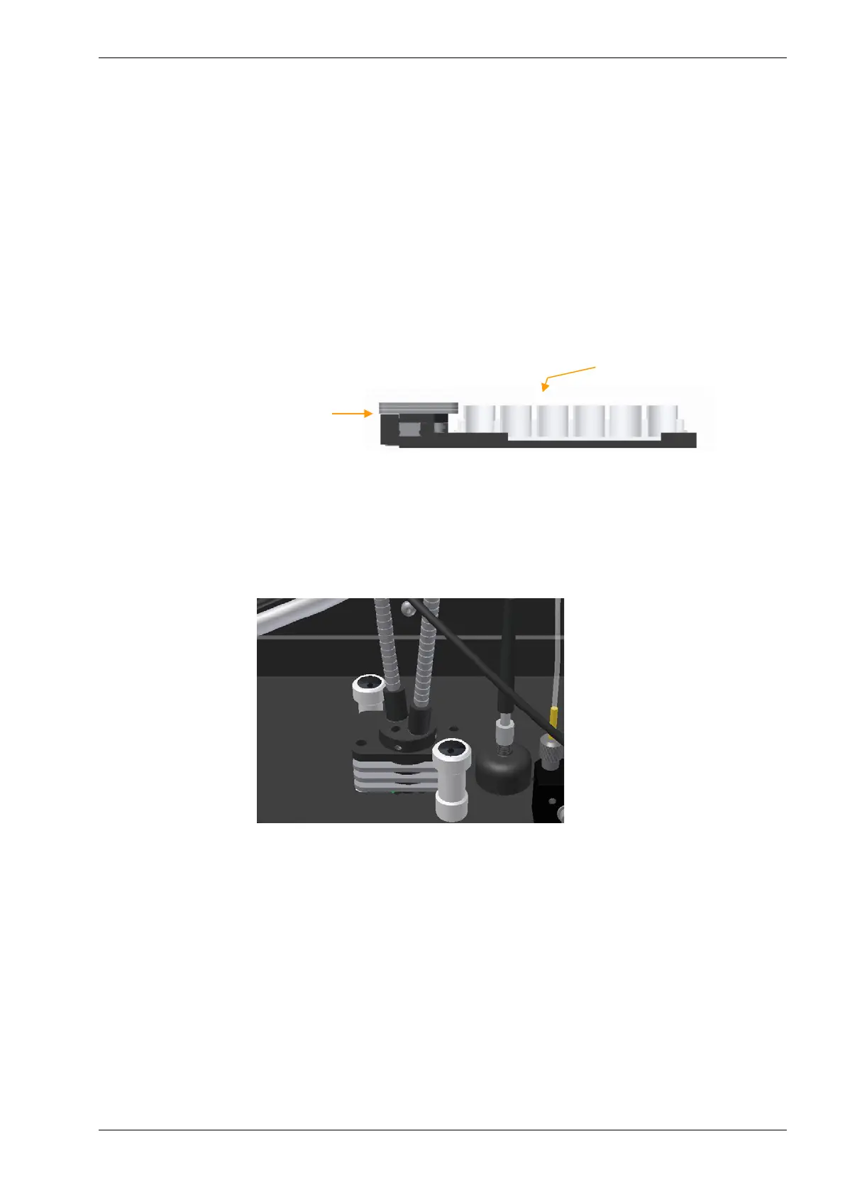
Figure 32: Front view of the plate carrier
Installation of spacers:
If you install spacers, first remove the injection needles (if any) from the optic and then remove the optic.
Install the appropriate number of spacers, using the positioning pins as a guide. Reinsert the optic.
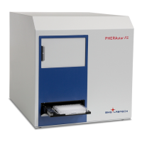
Figure 33: Example of spacers between
measurement head and bottom of reagent box
As a cross check (to ensure that the microplate can pass under the optic), push the plate carrier manually
into the instrument and slowly move it towards the optic. There should now be approximately 1.5 to 2 mm of
space between the optic and microplate.
3 spacers are needed in this
example to make the height of the
side of the plate carrier higher
than the microplate
Microplate (e.g. 24 well
plate) in the plate carrier