Omega Operating Manual BMG LABTECH
18/29 0415B0001G 2014-05-16
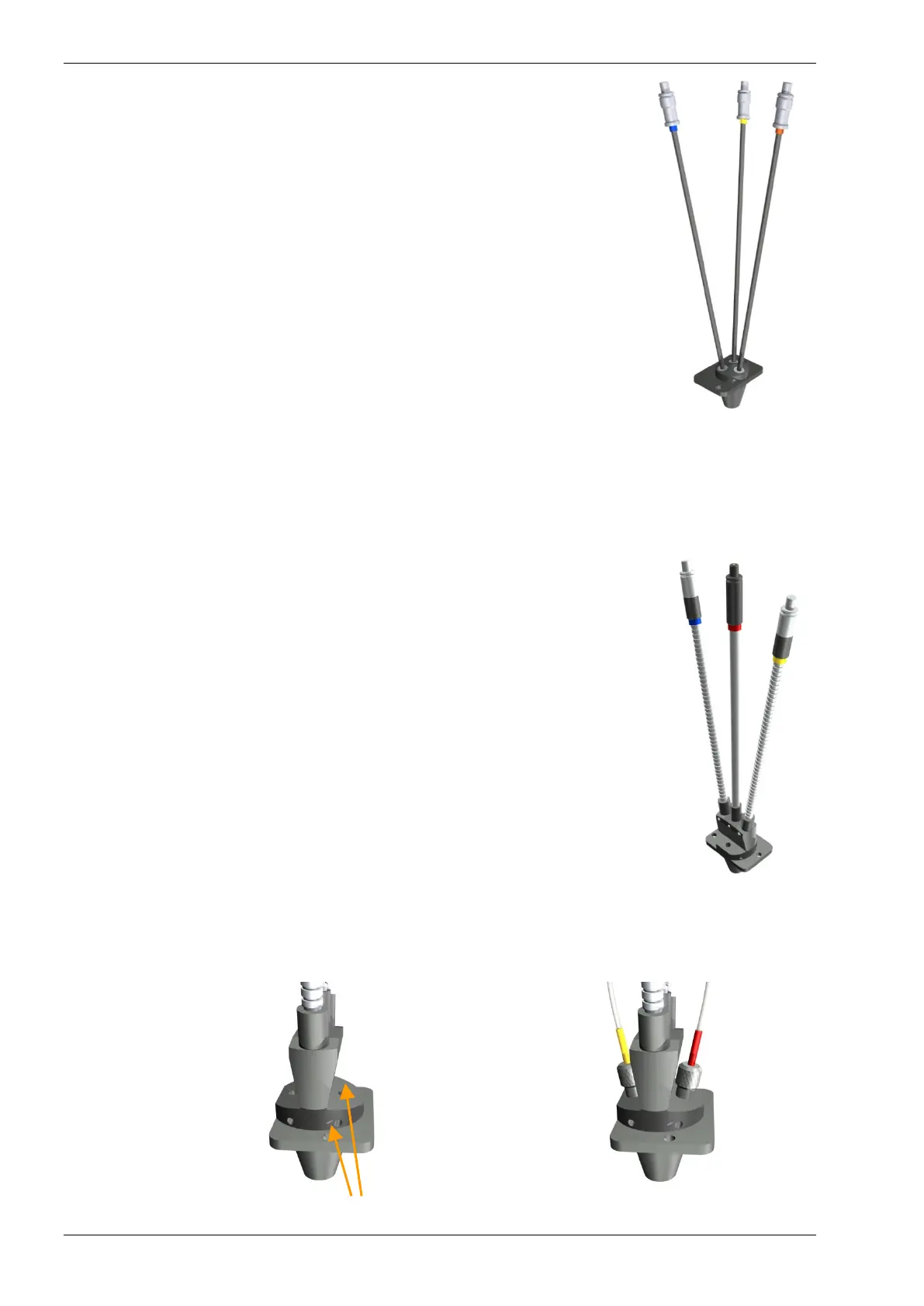
5.2.3 Fluorescence Polarization Optics
The light guides for fluorescence polarization are black and form a triangle at the
base of the optic.
Position the light guides as follows: right light guide into excitation position, left
light guide into the upper emission position (PMT 1) and the center light guide
into the lower emission position (PMT 2).
Only the POLARstar Omega can measure fluorescence polarization. It is
possible to upgrade the FLUOstar Omega to a POLARstar Omega.
Regarding filters for fluorescence polarization see chapter 5.3.3.
5.2.4 Dual Emission Optics
The dual emission optics are designed for assays in which you excite at one wavelength and measure two
emission wavelengths simultaneously (i.e. FRET). This is only possible in the POLARstar Omega because
this action requires two PMT's. The dual emission optics look like polarization optics, but are not capable of
polarization. The optic has to be installed in the same way as the polarization optic (figure 12).
5.2.5 Combination Optics
This optic can only be used with readers with PMT based absorbance, not with
spectrometer based absorbance.
The combination optic is made up of two liquid-filled light guides for fluorescence
intensity or luminescence and a quartz fiber for absorbance measurement (figure
13). It can be used for plate formats up to 96-well.
To position the measurement head with the quick-fix holders, see chapter 5.2
Installation and Changing of Optics.
For fluorescence measurements: excitation enters through the yellow marked light
guide and emission is measured through the blue marked light guide.
For absorbance measurements: The gray, red marked, absorbance light guide
excites from above and the absorbance is measured through the bottom optic.
In addition, for reader which have the luminescence option available,
luminescence can be measured through the blue marked light guide.
Figure 13: Combination optic
Regarding reagent injection: be careful when you position the needles in the measurement head (see figure
14) to avoid damage to the reagent needles as well as to the optic. The optional reagent injectors need to be
available.
Figure 14: Holes to position reagent needles in the measurement head
polarization optic