18
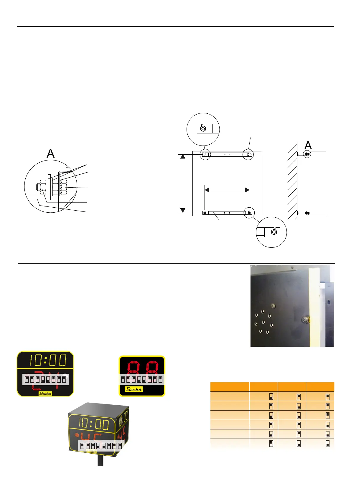
III - DIP switches setting
DIP switches have been set in factory; please check that they are set as follows.
1/ Open all the access hatches. To open the access doors, unscrew the
quarter-turn screws.
2/ DIP switches n°1 to 4 dene the part of scoreboard.
3/ DIP switches n°5 to 8 dene the scoreboard number.
EACH SCOREBOARD MUST HAVE A DIFFERENT NUMBER.
Quarter-turn screw
BT 6006 BT 6002
Scoreboard N° Dip 5 Dip 6 Dip 7
1 o ↓ on ↑ on ↑
2 on ↑ o ↓ on ↑
3 o ↓ o ↓ on ↑
4 on ↑ on ↑ o ↓
5 o ↓ on ↑ o ↓
6 on ↑ o ↓ o ↓
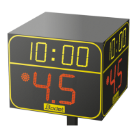
II - Wall mounting (only BT6002 and 6006)
For each 24 second display, the mounting kit is supplied with (915871) :
- 2 mounting brackets
- TH M10x30 screws
- HU M10 nuts
- Ø10 at washers
- Ø10 lock washers
1/ Mount the 2 brackets to the wall while respecting the drilling measurement (use the provided
template) (M10 screws and nuts are not suplied by BODET).
2/ Mount the 2 brackets to the display with TH M10x30 screws, HU M10 bolts and Ø10 washers
(see A).
Ø10 lock washer
Ø10 at washers
TH M10x30 screw
HU M10 nut
mounting bracket
Wall mounting
581 mm
360 mm
mounting brackets
BT 6008