The set-up of the two current controllers is identical and enables joint setting of am-
plification as well as the integral time for both controllers. For this, the parameters
Amplification 700 and Integral time 701 are available. The proportional and integra-
tion and component of the current controllers can be switched off by setting the pa-
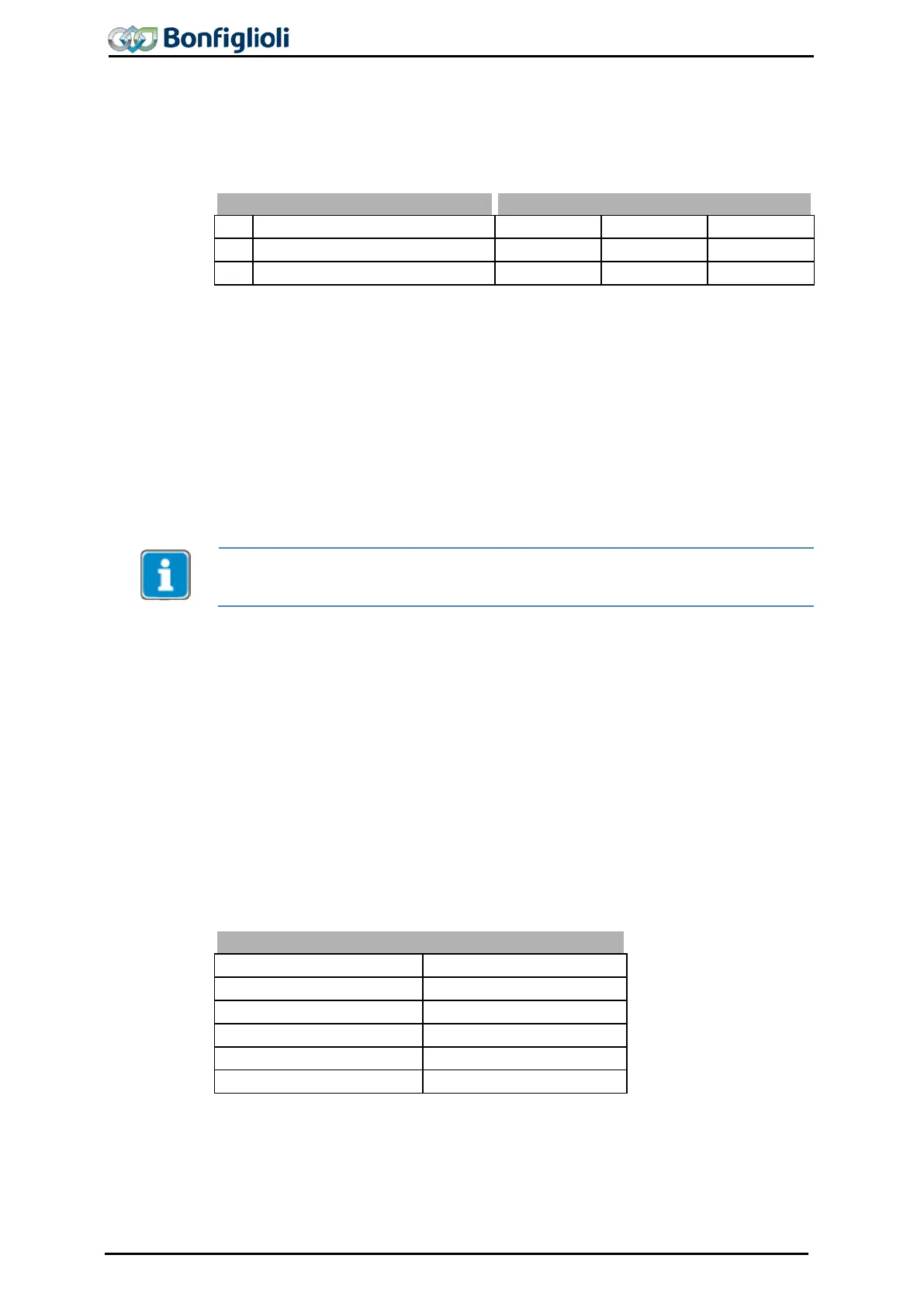
Parameter Settings
No.
Description Min. Max. Fact. sett.
700 Amplification 0.00 8.00 0.13
701 Integral time 0.00 ms 10.00 ms 10.00 ms
The guided commissioning has selected the parameters of the current controller in
such a way that they can be used without having to be changed in most applications.
If, in exceptional cases, an optimization of the behavior of the current controller is to
be done, the reference value jump during the flux-formation phase ca
this. The reference value of the flux-
forming current components leaps to the figure
Current during flux-formation 781
with suitable parameterization and then changes
controlled to the magnetizing current after the expiry of the Maximum flux-formation
time
780
. The operating point necessary for the adjustment demands the setting of
parameter Minimum Frequency 418
to the value 0.00 Hz, as the drive is accelerated
after magnetizing. The measurement of the step response, which is defined by the
r
atio of the currents mentioned, should be done in the motor supply line by means of
a measuring current transformer of a sufficient bandwidth.
The internally calculated actual value for the flux-forming current component cannot
be output via the analo
g output for this measure
ment as the time resolution of the
measurement is not sufficient.
To set the parameters of the PI controller, the Amplification 700 is increased first
until the actual value overshoots distinctly during the control process. Now, the am-
plification is reduced to about fifty percent again and then the
Integral time 701
synchronized until actual value overshoots slightly during the control process.
The settings of the current controllers should not be too dynamic in order to ensure a
sufficient reserve range. The control tends to increased oscillations if the reverse
range is reduced.
The dimensioning of the current controller parameters by calculation of the time con-
stant is to be done for a switching frequency of 2 kHz. For other switching frequen-
cies, the values are adapted internally so that the setting can remain un
all switching frequencies. The dynamic properti
es of the current controller improve if
the switching and scanning frequency increases.
The fixed time interval for the modulation results in the following scanning frequen-
cies of the current controller via parameter Switching frequency 400.
2 kHz
2 kHz
4 kHz 4 kHz
8 kHz 8 kHz
16 kHz 8 kHz
1)
This switching frequency can be set for parameter Min. switching frequency 401.
228 Operating Instructions ACU 06/13
 Loading...
