b
WARNINGS
•
Fill the condensate drain syphon (2) to a sufficient level and route the condensate drain hose correctly. Envisage suitable
condensate treatment systems.
•
The safety valve drain must be connected to a suitable disposal system. The manufacturer is not responsible for
possible flooding caused by intervention of the safety valve.
•
Systems charged with anti-freeze require the compulsory use of water shut-off devices.
•
The selection and installation of the system components is the task of the installer, who must observe all current
legislation and professional technical practices.
•
The expansion vessel of the heating circuit must ensure total absorption of the fluid expansion in the system.
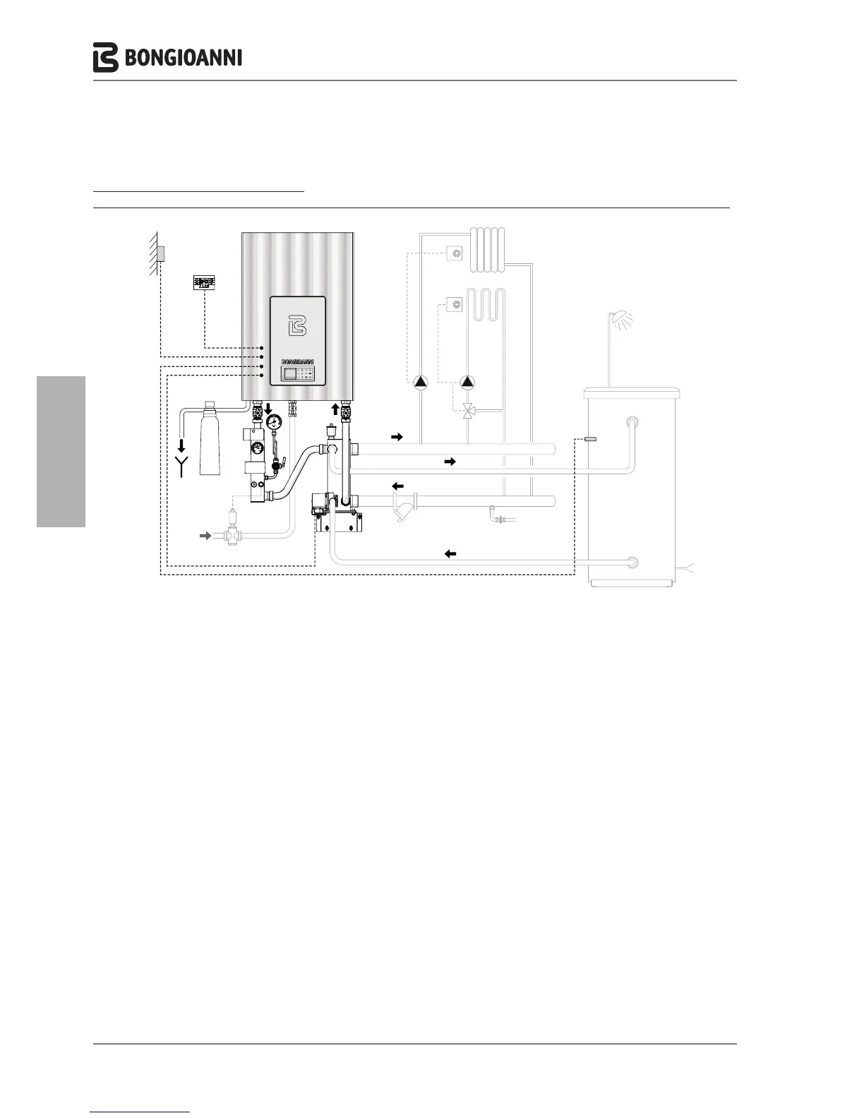
Multidea Evo and Multidea Evo M
ManagementofaHIGHTEMPERATUREzone,aLOWTEMPERATUREzoneandaremoteSTORAGETANK
eco
esc
menu
ok
Lunedi, 24. Settembre 2012
09.37
GAS
NC
Sc
TA1
TA2
ZBt
PR1
PR2
SE
CR
VM
Vic
IAF
(**)
SB
IAF
UAC
1
2
3
4
5
6
7
8
9
1 Boiler
2 INAIL safety module (*)
3 Hydraulic separator(*)
4 Pump (*)
5
Fuel shut-off valve
6 Remote storage tank (**) (man-
aged directly by the boiler)
7 System return manifold
8 System supply manifold
9 Screening filter
SE OTC sensor (*)
NC Condensate neutraliser (*)
CR Remote control
SB Storage tank sensor (*)
Sc Drain
ZAt High temperature zone
ZBt Low temperature zone
TA1 Room thermostat in high tem-
perature zone
TA2 Room thermostat in low temper-
ature zone
PR1 High temperature system pump
PR2 Low temperature system pump
VM Low temperature system mixing
valve
Sic
Fuel shut-off sensor
GAS Fuel supply
IAF Cold water inlet
UAC Hot water outlet
(*) Available as accessory.
(**)
In this configuration, the use of a
storage tank is recommended with
a suitable sized coil exchanger.
- 20 -