b
WARNINGS
The following is compulsory:
•
Use of an omnipolar thermal magnetic circuit breaker, line disconnector, in compliance with EN standards.
•
Observance of the connections L (Phase) - N (Neutral).
•
Use of cable sections of AT LEAST 1 mm
2
.
•
Use of an earthing wire that is at least 2 cm longer than those of the L (Phase) - N (Neutral) connections.
•
Reference to the wiring diagrams included in this manual for any type of electrical intervention.
•
Connections to an efficient earthing system (*).
•
NEVER use water hoses for earthing the appliance.
•
Great care to observe maximum absorption levels of the external circulation pumps (see “WIRING DIAGRAM” page 14).
(*) The manufacturer declines all liability for any damage caused by failure to earth the appliance or specifications
in the wiring diagrams.
N.B. The on-board fuse is 3.15A both for Phase and Neutral.
REMOTE ALARM
The outputs of terminals 11-12 supply a voltage-free contact (max 230Vac - 0.8A) for the management of an alarm signal.
This contact is activated each time an error/malfunction occurs on the boiler.
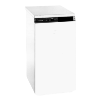
CONNECTION OF OUTSIDE SENSOR (OPTIONAL)
The outside sensor must be installed on the outside of the building,
on a flat surface in a north/north-east position (the coolest side)
and at a safe distance from the flues, doors, windows and areas
exposed to direct sunlight.
To install, proceed as follows:
- Remove the cover.
- Fix the sensor to the wall using two plugs.
- Make the electrical connections.
NOTE:
- Minimum cable section: 1 mm
2
.
- Maximum connection length: 50 m.
- Non-polarised connection terminals.
- Use shielded coaxial cables, with 2 wires and connect the
sheath to earth.
- 23 -