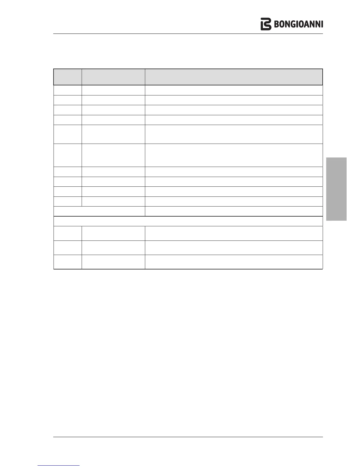
Ref. menu
line
Line title Meaning
6.1.2 Cascade min power Minimum available power in cascade
6.1.3 Single burner power Maximum power of single burner
6.1.4 Boiler for DHW Number of boilers also used for DHW
6.1.5 PI loop period Time interval for recalculating power requirements
6.1.6 Burner water flow delay
Delay of response of control algorithm according to hydraulic structure. In the case of cas-
cade configurations with disconnector, it is possible to balance the time in which a temper-
ature variation, read by the cascade sensor, is effectively received by the control board.
6.1.7 Different boiler size
Enables/Disables algorithm-based control of cascade configurations of boilers with
different outputs (e.g. in the presence of a low power generator dedicated to DHW pro-
duction). In the case of combining several generators of the same output, this algorithm
does not need to be enabled.
6.1.8 Cascade pump speed max Setting of maximum admissible speed for cascade pumps
6.1.9 Cascade pump speed min Setting of minimum admissible speed for cascade pumps
6.2 Cascade info Display of information on the cascade configuration
6.3 Cascade autodetect Start of cascade auto-configuration process.
7. RESTORE FACTORY SETTINGS Restores factory settings
8. BOILER TYPE
8.1 Wall Hung Boiler
Setting of type of boiler as “Wall-hung” “Multidea EVO” and selection of output model
Change to type of gas used
8.2 Floor standing boiler 1
Setting of type of boiler as “Floor-standing” “Alubongas 1” and selection of output model
Change to type of gas used
8.3 Floor standing boiler 2
Setting of type of boiler as “Floor-standing” “Alubongas 2” and selection of output model
Change to type of gas used
- 39 -