13 On Off On On Off Off
14 Off On On On Off Off
15 On On On On Off Off
16 Off Off Off Off On Off
Table 5.1: Keypad Address Settings
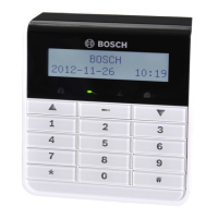
IUI-AMAX-LED8 and IUI-AMAX-LCD8 keypads can only be set to address 1 or address 2 through
the address jumper.
– Jumper not short-circuited: Address 1.
– Jumper short-circuited: Address 2.
Address 1
Jumper not short-circuited:
Address 2 Jumper short-circuited (both metal pins are covered)
Table 5.2: Keypad Jumper Settings
See also
– Keypad Address Settings, page 11
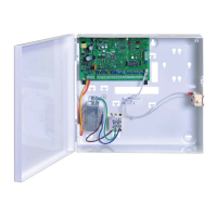
Wiring and Installation
Connect the keypad to the bus of the alarm control panel. See , page 13
– R: provides 12V power supply for the keypad and other devices.
– B: ground conductor.
– G: for the alarm control panel to transmit data to external devices.
– Y: for external devices to transmit data to the alarm control panel.
5.1.3
12 en | Optional Modules and Peripheral Devices
AMAX panel 4000 / AMAX panel 4000
EN
2013.07 | 03 | F.01U.267.112 Installation Guide Bosch Sicherheitsysteme GmbH
 Loading...