1 689 979 792 2010-02-24| Robert Bosch GmbH
Operation | BAT 121 | 17BAT 121 | 17 | 17 en
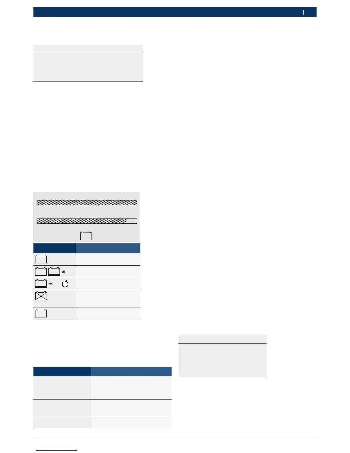
5.1.2 Battery test evaluation
BATTERY-TEST
TEST RESULT
VOLTAGE: 12,91V
START CAPACITY: 105%
BATTERY: GOOD
300A DIN >0°C E
The results from the Battery-Test provide the following
information:
R Voltage
R Start Capacity
R Overall battery condition in the form of text:
$ Good battery
$ Good battery / Charge the battery
$ Charge the battery / repeat the Battery-Test
$ Battery unserviceable
$ Battery unserviceable / Short circuit between
battery cells
¶ E provides access to graphical representation of
charge status, starting capacity and battery status.
STATE OF CHARGE:
START CAPACITY:
0 50 100%
0 50 100%
+
-
OK
E
Symbol Battery condition
+
-
OK
Good battery
+
-
OK
+
-
Ah
Good battery
Charge the battery
+
-
Ah
Charge the battery
Repeat the Battery-Test
+
-
Battery unserviceable
Short circuit between
battery cells
+
-
?
Check parameters
i The Start output indicates the ratio of the battery’s
measured cold-start current to the entered cold-star-
ting current. The start output may exceed 100 %.
5.1.3 Notes on problems
Message Action to be taken
Battery voltage
interference: Switch off
engine / Radio off/ Elec-
trical equipment off
Switch off electrical equipment
(refer also to Section 4.3) and
repeat battery test
Contact problems:
Check positive terminal /
Check negative terminal
Check connection to battery posts
and clean battery posts if necessary
Check parameter Check parameter
and repeat battery test
5.2 Alternator-Test
The Alternator-Test is carried out in 2 steps.
Step 1 "Regulator Volt"
The generator regulator ensures correct charging during
driving by regulating the final charging voltage (Regu-
lator Volt) of the battery. This final value is recorded
automatically by the BAT 121 as soon as the increase
in voltage reaches the steady state. This final state is
reached sooner when all consumers are switched off.
Step 2 "Ripple"
The battery voltage is characterised by the ripple of a
certain pattern from an intact alternating-current ge-
nerator. Test information is obtained by analysing this
pattern at idle speed in combination with a battery
capable of starting the engine and powering the rear-
window heater.
i Carry out a Batter-test before conducting the Gene-
rator-Test. The connecting terminals of the battery
tester should be connected directly to the poles of
the battery for the Generator-Test as well.
5.2.1 Alternator test procedure
1. Start the alternator test with E.
2. Use the keys and to set the regulator tempera-
ture >0 °C or <0 °C for the Alternator-Test.
3. Then start the engine of the vehicle.
4. Switch off all consumers in the car for Step 1 "Regu-
lator Volt".
i A result can be obtained more quickly for Regula-
tor Volt at a higher engine speed.
5. Switch on the rear-window heater as the consumer
for Step 2 "Ripple".
! The engine must now turn over at the idling speed.
The following information is displayed by the battery
tester (example):
ALTERNATOR-TEST
TEST-RESULT
RIPPLE GOOD
REGULATOR VOLT: 14.22V
GOOD
REGUL. TEMP >0°C