Do you have a question about the Bosch Control 8310 and is the answer not in the manual?
Explains signal words and symbols used for warnings and instructions.
Provides essential safety guidelines for installation and operation.
States compliance with British, European, and national requirements.
Details proprietary and open-source software used in the product.
Lists required tools and materials for installation and maintenance.
Outlines items included in the product package upon delivery.
Lists available optional accessories for the control unit.
Describes the extended control unit's capabilities and master unit requirement.
Specifies the approved use of the control unit for extending a master control unit.
Defines key terms like Heat source, Qualified person, Contractor, and Module.
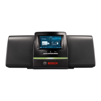
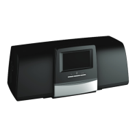
Identifies and describes the physical components and controls of the control unit.
Details settings, operation, commissioning, fault display, and troubleshooting.
Explains how to view the system overview on the master control unit.
Guides on navigating and selecting networked control units in the system overview.
Explains how faults are indicated and where to find malfunction notices.
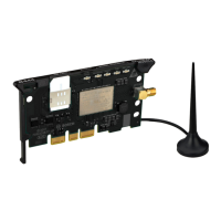
Lists all modules installed in the control unit and their functions.
Provides guidance on inserting and numbering additional modules in available slots.
Details the connection and power supply for modules inserted into slots.
Describes the FM-AM module's role in controlling alternative heating appliances.
States that the FM-CM module cannot be used.
Explains the FM-MM module's function for regulating independent heating circuits.
Describes the FM-MW module for controlling heating circuits and DHW heating.
Details the FM-RM module for mounting components on a rail.
States that the FM-SI module cannot be used.
Notes that a central module is not possible with this control unit.
Explains operation via master control unit and PC connection for service.
Details the NM582 module's function in supplying voltage to components and safety features.
Describes the BM592 module providing 24V power supply for components.
Recommends wall mounting for the control unit and specifies installation height limits.
Highlights safety precautions for connecting the control unit to the heat source.
Explains Modbus RTU protocol usage and connecting compatible components.
Provides critical safety warnings and guidelines for electrical connections.
Details the various connections on the user interface, including USB and network ports.
Refers to chapter 11 for options on connecting to other control units or networks.
Explains the 230V power supply requirement for modules and module-to-module voltage distribution.
Mentions that other connections may be needed depending on module function.
Guides on assigning unique addresses to networked control units for proper communication.
Explains the use and setting of terminating resistance jumpers for BUS connections.
Lists essential pre-commissioning steps and system checks for the control unit.
Describes the wizard for initial setup and essential operation settings.
Covers settings for screensavers, language, date/time formats, and building insulation.
Explains how modules are automatically recognized or can be set manually.
Outlines functions for linking control units, connecting to the Internet, and establishing networks.
Guides on creating networks using LAN interfaces and connecting multiple control units.
Details the process of establishing a network using LAN cables and correct addressing.
Describes the process of coupling control units on the CBC BUS and its indicators.
Explains the effects of reset functions on main menu and service menu settings.
Instructs on accessing the service menu for advanced functions and settings.
Details functions for saving/loading system data via USB stick.
Explains using a service adapter for PC-based operation and monitoring.
Guides on updating control unit software, including for networked systems.
Describes saving and loading device configurations using a USB stick.
Explains how faults are indicated and automatically reset after rectification.
Lists technical data and specifications for the Control 8310 unit.
Provides a template for documenting the commissioning process and checks.
| Brand | Bosch |
|---|---|
| Model | Control 8310 |
| Category | Control Unit |
| Language | English |
