Information for the user
5
Control 8310 – 6720856493 (2022/07)
3 Information for the user
HSafety precautions
▶ Observe safety instructions in the documents of the control units
series Control 8000.
These instructions contain important information for the system user
regarding safe operation of the control unit.
▶ Observe the operating instructions for the master control unit and
the heat generator.
Depending on the software version, the display and menu items shown
in the instructions may differ from those in the control unit.
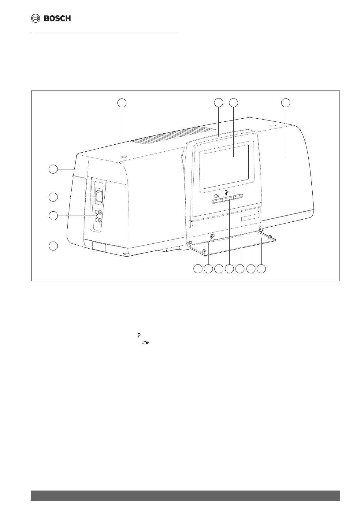
3.1 Overview of the control unit and the control elements
Fig. 1 Overview of control unit
[1] Housing lid/cover
[2] Remote control
[3] Cover
[4] Front cover
[5] Not used
[6] Reset button (changed function)
[7] Chimney sweep button (without function)
[8] Manual operation button (changed function)
[9] USB connection (e.g. for service purposes)
[10] LED-Status display
[11] Data plate
[12] F1-, F2-Circuit breaker
[13] ON/OFF switch
[14] Rear panel
Function keys
As the control unit is operated via the master control unit, the original use
of the keys ( Fig 1, [6], [7] and [8]) is deactivated. They are used only
for service purposes ( chapter 13, page 16).
System status, function status, component status
The status of the modules, the functions and the system components
installed in the control unit Control 8310 are displayed via the status
display LED- ( Fig 1, [10], page 5):
• Green = system in automatic mode
• Blue flashing = software update
• Green flashing = pairing
(establishing connection with the control unit)
• Yellow = system in manual operation, service display or blocking fault
• Yellow flashing = Control unit coupling
•Red = fault
0010027290-001
reset
3
6 59 78
10
12
11
1
2
1
4
13
14