Information for experts
7
Control 8310 – 6720856493 (2022/07)
Heat production
This is only displayed if a function module FM-AM is installed. To open the
overview:
▶Tap on Heat production ( Figure 4, [1]).
System
The system displays the heat distribution of the functions on the selected
control unit connected. To open the overview of functions on the
selected control unit connected.
▶Tap on System ( Figure 4, [3]).
Networking symbol
The symbol indicates that is located in the control unit overview of a slave
control unit.
To return to the master control unit or to go to another control unit:
▶ Tap on the networking symbol ( Figure 4, [4]).
▶ Select the control unit as described above.
3.3 Troubleshooting
Faults relating to the control unit are indicated by the LED status display
and displayed in the master control unit.
▶ Observe the malfunction notices in the master control unit.
4 Information for experts
HNotices for the target group
These installation instructions are intended for gas, plumbing, heating
and electrical contractors. All instructions must be observed. Failure to
comply with instructions may result in material damage and personal
injury, including danger to life.
▶ Read the installation, service and commissioning instructions
(heat source, heating controller, pumps, etc.) before installation.
▶ Observe the safety instructions and warnings.
▶ Follow national and regional regulations, technical regulations and
guidelines.
▶ Record all work carried out.
HSafety precautions
▶ Observe safety instructions in the documents of the control units
series Control 8000.
5 Modules and their function
5.1 Fitted modules
All modules fitted in the control unit are listed in the following table.
The description also includes the FM-MM and FM-MW modules.
Table 2 Modules and their functions
[X] Standard equipment
[O] Accessory
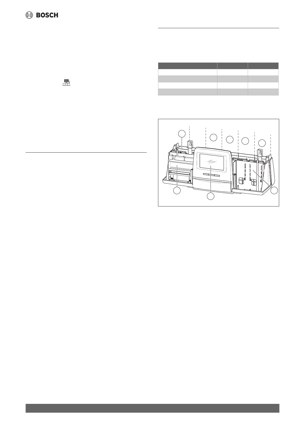
Fig. 5 Overview of slots
[1] Slot A (not in use)
[2] Slot B (power supply module)
[3] Slot 1
[4] Slot 2
[5] Slot 3
[6] Slot 4
[7] Slot C
[8] Remote control (without display)
5.1.1 Notice regarding installed modules
The additional modules can be inserted in any free slot 1...4. In doing so,
make sure that the power supply leads from module to module. We
recommend that you insert the modules one by one from left to right to
ensure the heating circuits are logically numbered.
When using certain modules, it is advisable to mount them at specific
slots ( chapter 5.2, page 8).
Module Slot 8310
BC831 user interface Remote control X
NM582 power supply module B X
Function module (e.g. FM-MM) 1...4 O
Function module FM-RM C O
0010005505-001
3
4
5
6
1
8
7
2