Analog and Frequency Inputs | 12
Bosch Motorsport DDU 9 95/148
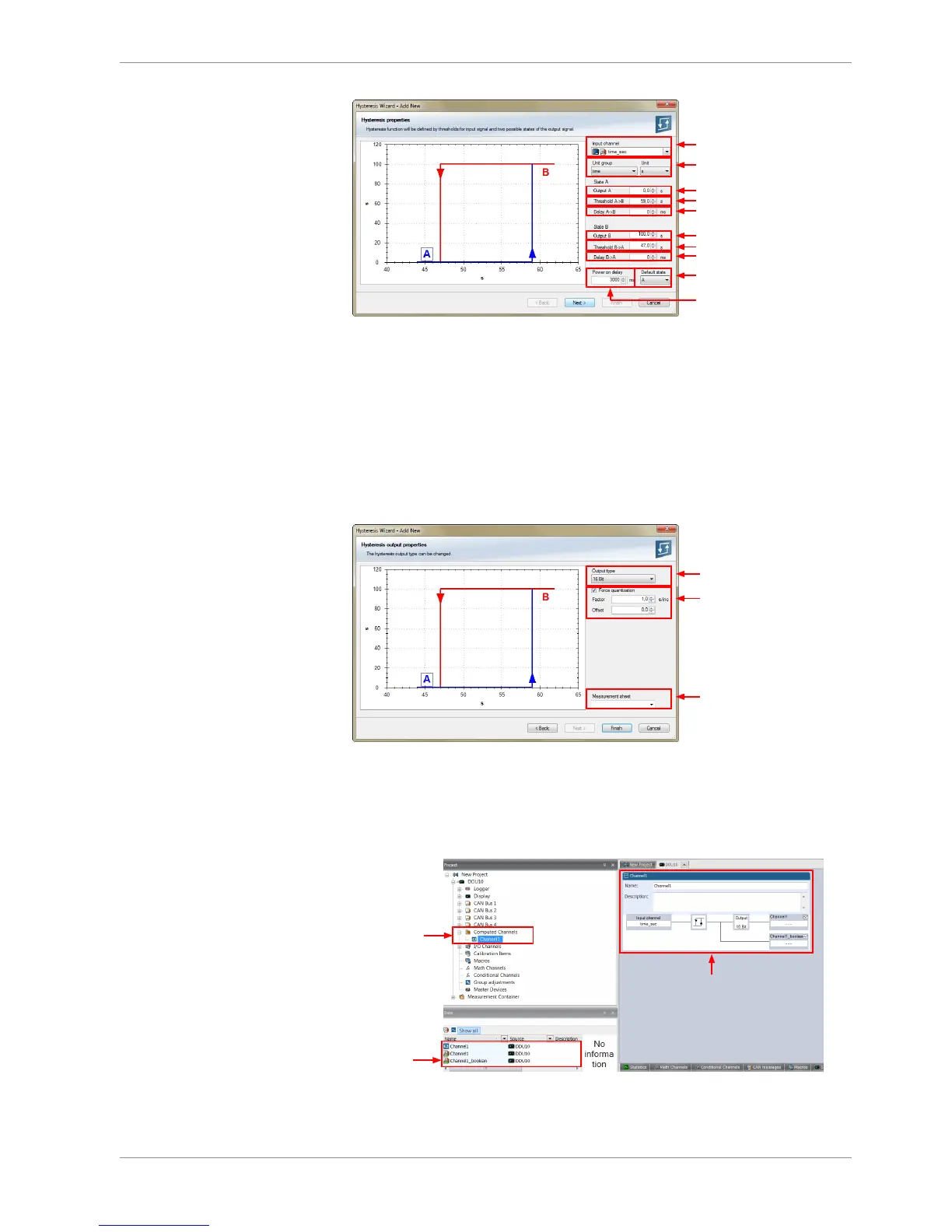
a)
b)
c)
d)
e)
f)
g)
h)
i)
j)
a) Choose input measurement channel.
b) Choose unit group and unit of output.
c) Enter output value of state A in the unit selected in b).
d) Enter threshold value when state changes from A to B.
e) Enter delay time when state changes from A to B.
f) Enter output value of state B in the unit selected in b).
g) Enter threshold value when state changes from B to A.
h) Enter delay time when state changes from B to A.
i) Enter time when the hysteresis function is activated after vehicle´s startup.
j) Enter the channel´s state (A or B) at startup.
3. Click ‘Next’ when done.
The second part of the ‘Hysteresis Wizard’ opens.
Choose data type of
the measurement variable
Check the box to force the
channel's quantization if the
quantization should be a fixed
value in the whole CAN system
Enter name to automatically
create a new measurement sheet
4. Click ‘Finish’ when done.
5. Enter channel name and description.
6. Click ‘OK’ when done.
The channel is inserted into the DDU 9 Project Tree.
Channels available
in Computed sources
Available
measurements
for channel
Calculation of hysteresis
channel