12 | Analog and Frequency Inputs
78/148 DDU 9 Bosch Motorsport
12 Analog and Frequency Inputs
Analog inputs
– 0 to 5 V
– 12 bit A/D converter
– Switchable 3.01 kOhm pull-up resistor
– 8 kHz acquisition rate, up to 1 kHz recording rate
– Linear phase digital filter
Frequency inputs
– 5 V Hall-effect type, 2.5 V trigger level
– 20 kHz max. frequency
– 10 ms measurement window
12.1 Analog inputs
12.1.1 Measurements channels
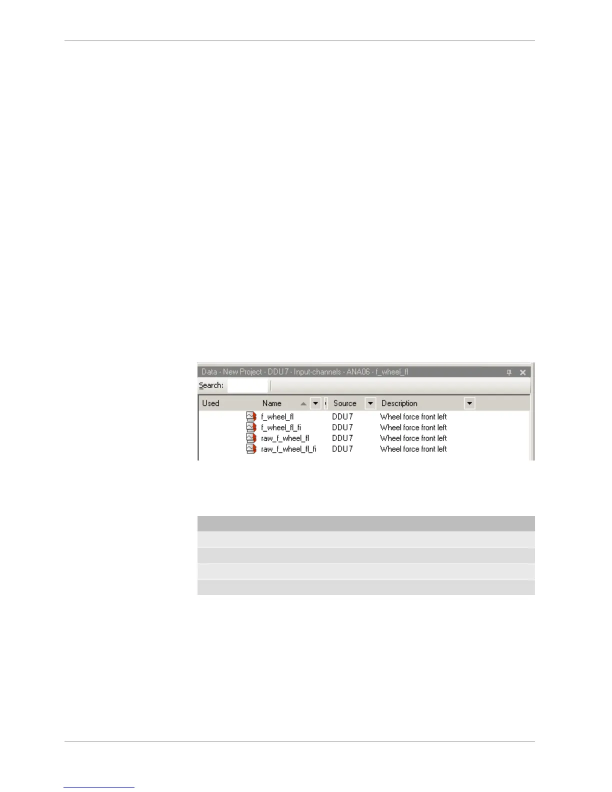
For each analog channel, several ‘subchannels’ are available.
Measurement labels with the characters ‘raw’ show the exact values in mV.
Measurement labels with the characters ‘_fi’ show filtered values.
The word ‘name’ in the table is a placeholder for the channel’s name.
Measurement label Function
raw_name mV value of sensor
raw_name_fi Filtered mV value of sensor
name Physical value of sensor
name_fi Filtered physical value
Filtered channels are routed through digital low pass filters:
– DDU 9 uses A/D converter oversampling and digital filtering to recording rate
– Digital filters eliminate ‘out-of-band’ noise
– Cut-off frequency automatically adjusted to recording rate
– Linear phase – no signal distortion
– Latency compensation – no filter delay in recorded data