6 720 800 844 (2012/02)
10 | Technical data for the accessory item
2.5 Sample system
Fig. 3 Simplified system scheme (see technical guides for installation illustration and further options)
AF Outside temperature sensor
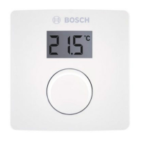
FB 10 Remote control
FB 100 Remote control
FK Flat-plate collector
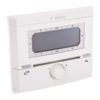
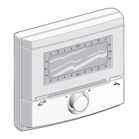
FW 120 Weather-compensated controller with
solar control
HK Heating circuit
HP Heating circuit pump
HW Low loss header
IPM 1 Module for one heating circuit
ISM 1 Module for solar DHW heating
KW Cold water connection
M Mixer servomotor
MF Flow temperature sensor, mixed
heating circuit
P Circulation pump for heating circuit
SP Solar circuit pump
S...solar Solar combi cylinder
SF Cylinder temperature sensor (NTC)
T
1
Collector temperature sensor
T
2
Cylinder temperature sensor on the
heating water side, bottom
TB Temperature limiter
TWM Thermostatic DHW mixer
VF Common flow sensor
WW DHW connection
1) The FW 120 can be mounted in the
heat source or on the wall.
2) Either FB 10 or FB 100
6 720 800 004-01.1O
WW
TWM
KW
S...solar
SP
SF
HK
MF
TB
M
P
1)
FW 120
FB 10
VF
230V AC
T
2
AF
FK
230V AC
ISM1
2)
T
1
FB 100
2)
HP
1)
FW 120
HW
IPM1
230V AC
 Loading...
