18 en | Installing the Pendant Arm Wall, Corner, and Mast (Pole) Mounts VG4 Modular Camera Series
F.01U.216.010 | 8.0 | 2011.02 Installation Manual Bosch Security Systems, Inc.
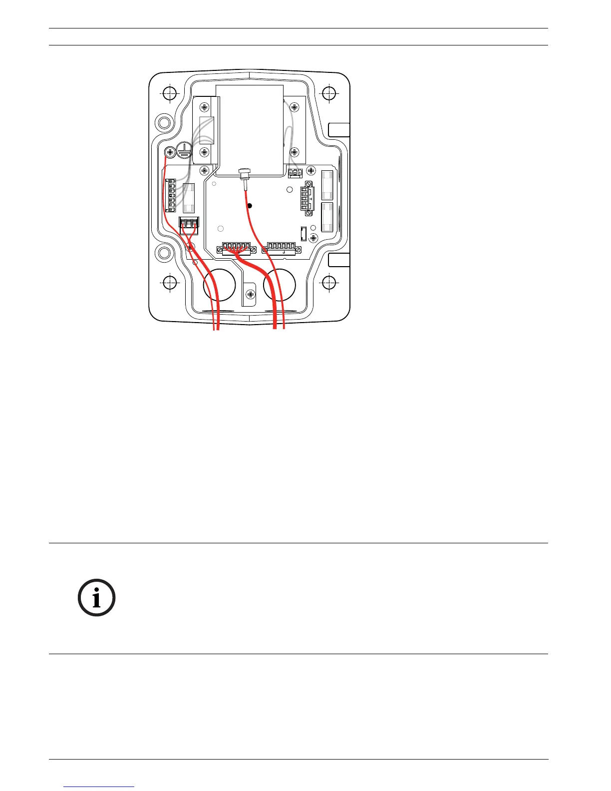
Figure 2.2 Pendant Arm Power Supply Box
1. Route all video, control, and alarm wires through the conduit fitting on the right side of
the power box. See Section 5 Cable and Wire Standards, page 88, for coax, UTP, and fiber
optic specifications and distances.
2. Route the high voltage 115/230 VAC lines through the conduit fitting on the left side of
the box. The Power Supply Box with a transformer comes with a barrier that separates
the high voltage side on the left, from the low voltage 24 VAC side on the right.
3. Cut and trim all wires with sufficient slack to reach their connector terminals in the box,
but not so long as to be pinched by or to obstruct closing the Pendant Arm. See
Figure 2.2, Page 18, above, for the connector locations.
4. Attach the supplied 3-pin Power Plug to the incoming power wires. See connector P101
in Table 2.1, Page 21, for wire connections.
5. Attach the supplied 6-pin Control Data I/O Plug to the incoming control wires. See
connector P106 in Table 2.1, Page 21, for wire connections. This step is not required with
Fiber Optic models, since control passes through the fiber optic cable.
6. Attach a BNC connector to the incoming video coax cable. If using UTP for video or
installing an Ethernet model, attach an RJ45 plug to the incoming UTP cable. If installing
a Fiber Optic model, attach an ST fiber plug to the optic fiber cable. See Section 5 Cable
and Wire Standards, page 88, for the different methods of transmitting video and control
protocols, and wire specifications.
GND T XD
R XD
C+
C-
24 VAC
P101
P106 P105
P107
XF102 XF103
XF101
5 4 3 2 1
J103
J102
J101
(LED)
HTR DOME
24V NC 24V
GND T XD
R XD
C+
C-
NOTICE! If “daisy chaining” a series of AutoDomes, a terminating resistor is required in the
last dome of the series. The Bosch Power Supply Box is supplied with a 100 ? terminating
resistor located between the Biphase terminals C- and C+ (pins 1 and 2) of the P106 control
connector. Remove the resistor from all but the last AutoDome power box. The maximum
number of AutoDomes that can be daisy chained is four (4). If using the RS485 protocol for
control, the terminating resistor must be moved from the Biphase C+ and C- (pins 1 and 2)
terminals to the RXD- and TXD+ terminals (pins 4 and 5) of the P106 control connector of the
last AutoDome power box.
 Loading...