VG4 Modular Camera Series Installing the Pendant Arm Wall, Corner, and Mast (Pole) Mounts | en 19
Bosch Security Systems, Inc. Installation Manual F.01U.216.010 | 8.0 | 2011.02
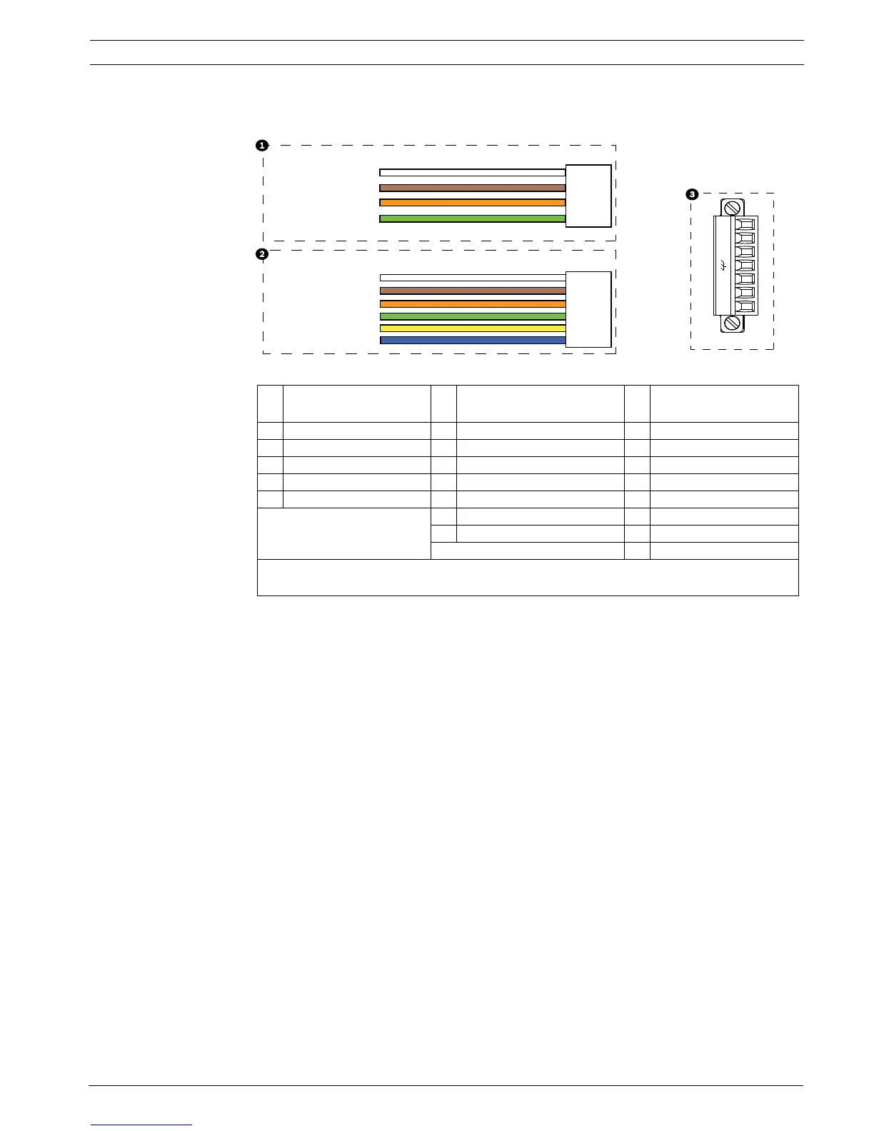
7. If you are connecting alarm inputs and outputs, attach the supplied 4- and 6-pin Alarm
Connectors with flying lead wires to the appropriate incoming alarm wires.
Figure 2.3 Alarm and relay connectors
8. If you are connecting supervised alarms and relays, attach the supplied 7-pin Relay
Connector to the appropriate incoming wires. See Figure 2.3, Page 19, above, for the wire
connections. See Section 6 Alarms and Relay Connections, page 98 for more details about
wiring alarms and relays.
1 4-pin Alarm Connector
(P102)
2 6-pin Alarm In Connector
(P103)
3 7-pin Relay Connector
(P104)
Pin Description Pin Description Pin Description
1 Alarm Out 1 1 Alarm In 3 1 Normally Open
2 Alarm Out 2 2 Alarm In 4 2 COM
3 Alarm Out 3‡ 3 Alarm In 5 3 Normally Closed
4 Alarm Ground 4 Alarm In 6 4 Earth Ground
5 Alarm In 7 5 Analog Alarm 1
6 Alarm Ground 6 Analog Alarm 2
7Ground
‡
The Alarm Out 3 (on the P102 connector) is the dedicated low pressure alarm for VG4 100 Series
AutoDome cameras.
1
1
2
3
4
5
6
2
3
4
N.O. COM N.C. A1 GND A2
1
PIN
PIN
P102
P103
P104
WHITE
ORANGE
BROWN
GREEN
WHITE
ORANGE
BROWN
GREEN
YELLOW
BLUE
2
3
4
5
6
7
 Loading...