INTEGRUS | Installation and User Instructions | Connecting to an Integrus transmitter en | 8
Bosch Security Systems | 2005-04 | 9922 141 70164en
3 Connecting to an Integrus
transmitter
3.1 Connecting interpreters desks
LBB 3222/04 directly
An Integrus transmitter requires the LBB 3422/20
Integrus audio input and interpreters module to direct-
ly interface with one or more LBB 3222/04
interpreter desks. This module must be mounted in
the transmitter housing (see the Integrus installation
manual).
Up to 12 interpreter desks can be loop-through con-
nected to the module. The system cable of the first
interpreter desk is connected to the 25-pole sub-D
connector on the Integrus audio input and interpreters
module. The system cables of the next desks are loop-
through connected to the system input plugs on the
preceding desks.
The floor signal for the interpreters desk is connected
to the Aux-Left input of the Integrus transmitter with
an XLR connector. The floor signal can come from a
CCS 800 analogue conference system (i.e. the line out-
put cinch connector, see the CCS 800 installation man-
ual) or from an external audio source, such as an audio
mixer.
The DIL switches on the Integrus audio input and
interpreters module must be set to ‘Direct connection
to LBB 3222/04 interpreter desks’ (see section 2.2).
The ‘Aux. Input’ mode of the Integrus transmitter must
be set to ‘Emergency/Mono’ (see the Integrus installa-
tion manual).
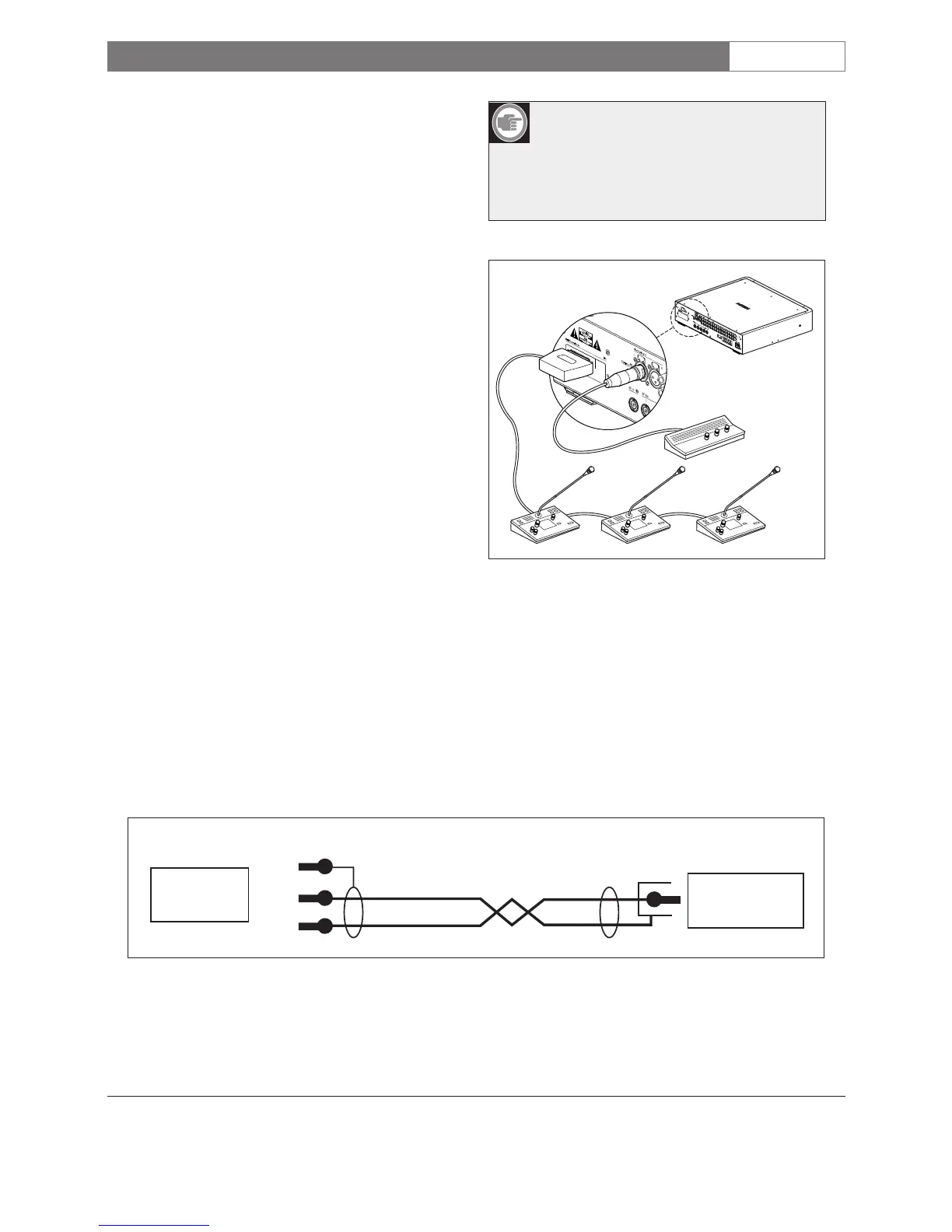
Note: To connect the floor signal, a cable
with a male XLR connector and a male
cinch connector must be made. See
figure 3.1 and figure 3.2 for the wiring.
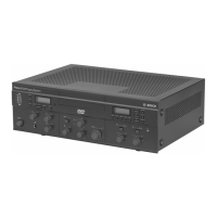
Figure 3.1 Connecting one or more LBB 3222/04
interpreter desks directly to the modular
IR transmitter
Figure 3.2 Wiring of the cinch to XLR connecting cable