44 en | Typical System Configurations MIC IP ultra 7100i │ MIC IP starlight 7100i
2019-07-03 | 0.17 | Installation Manual Bosch Security Systems
14 Typical System Configurations
14.1 Typical IP Configuration with High PoE midspan (no I/O
connections)
Figure14.1: System Configuration with a midspan (no input or output connections)
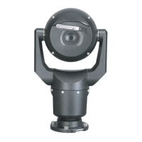
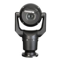
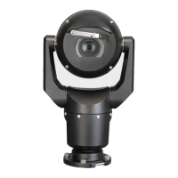
1 MIC camera 2 MIC Hinged DCA (MIC-DCA-Hx)
3 High PoE (Network) cable (Cat5e/Cat6
Shielded Twisted Pair (STP)) (user-
supplied) between the camera and the
High PoE Midspan
4 High PoE Midspan
5 Data-only IP cable (Cat5e/Cat6
Shielded Twisted Pair (STP)) (user-
supplied) between the High PoE
Midspan and the head-end network
Note: The total length of Cat5e/Cat6 Shielded Twisted Pair (STP) cable must be less than 100
m (328 ft) between the camera and the head-end system.

 Loading...
