Bosch Security Systems | 2006-06 | 9922 141 10377 en
Plena Voice Alarm System | Installation and User Instructions | Equipment en | 29
5.2 Installation
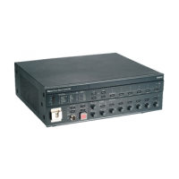
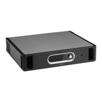
The voice alarm controller is suitable for table-top and
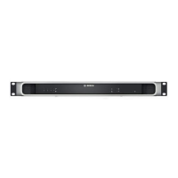
19-inch rack-mounting installation. Two brackets for
rack-mounting are supplied. See figure 5.2 for
installation details.
Make sure that there is a free space of at least 100 mm
on both sides of the unit for ventilation. The voice alarm
controller has an internal fan, which is regulated to keep
the temperature inside the unit within the safe operating
area.
5.3 External connections
5.3.1 Emergency microphone
The voice alarm controller has 1 connector for an
emergency microphone. A hand-held emergency
microphone is supplied with the voice alarm controller.
See figure 5.3 for installation details. Turn the lock ring
clockwise to lock the plug.
5.3.2 Call station
The voice alarm controller has 2 sockets for
LBB1956/00 Call Stations. Use Cat-5 Ethernet cables
with RJ45 plugs to connect call stations to the voice
alarm controller. When the system requires more than 2
call stations, use the system sockets on the call stations
to make loop-throughs. See figure 5.4 for connection
details.
If the cable between the call station and the voice alarm
controller is longer than 100 m, the call station must be
connected to a 24 V(DC) power source (see section 7.2.2).
figure 5.2: Brackets for rack-mounting
figure 5.3: Connecting the emergency microphone
0
-
+
-
+
0
dB
-
6
dB
-
2
0d
B
P
ro
ces
s
o
r
res
et
Net
w
ork
C
all/
E
M
G
M
us
i
c
/
S
pare
G
ro
und
s
h
o
rt
I
nput
M
ai
ns
Bat
t
er
y
Z
one1
Z
on
e2
Z
on
e3
Z
on
e4
Z
o
n
e5
Z
o
ne6
A
l
a
r
m
Z
o
n
e
s
e
l
e
c
t
Plena
V
oice
Al
arm Controll
er
F
a
ult Ind
i
ca
t
o
r
s
C
D
/
T
uner
Aux
S
e
le
c
t
Z
o
n
e
s
e
l
e
c
t
I
nd
i
ca
t
o
r
tes
t
E
M
G
m
i
c
A
l
er
t
m
es
s
a
g
e
A
l
a
r
mm
es
s
a
g
e
A
l
l
ca
l
l
Zo
n
e
1
Z
o
n
e
2
Z
o
n
e
3
Z
on
e
4
Z
on
e
5
Z
o
n
e
6
F
a
ul
t
EMG
A
c
k
R
eset
A
B
D
i
sa
b
l
ed
M
es
s
ag
e
E
M
Gm
ic
R
C
P
R
o
uter
0
-
+
-
+
0d
B
-
6
d
B
-
2
0
d
B
P
r
o
c
es
so
r
r
e
s
e
t
N
e
t
w
o
r
k
C
a
l
l
/
E
M
G
Mus
i
c
/
Sp
a
r
e
Gr
o
un
d
s
h
o
r
t
I
n
p
ut
M
a
i
ns
B
a
t
t
e
ry
Z
o
n
e
1
Z
o
n
e2
Z
o
n
e
3
Z
o
n
e4
Z
o
ne5
Z
o
ne
6
A
la
r
m
Zon
e
s
ele
c
t
P
len
a
V
o
i
c
e
A
larm
C
o
n
t
r
o
l
le
r
F
a
ult
I
nd
ica
t
o
r
s
C
D
/Tu
n
er
A
ux
S
e
l
e
c
t
Zon
e
s
ele
c
t
I
n
d
i
ca
t
o
rt
e
s
t
E
M
Gmi
c
A
l
e
r
t
mess
a
g
e
A
l
a
r
m
mes
s
a
g
e
A
l
l
c
a
l
l
Zon
e
1
Zon
e
2
Zon
e
3
Zon
e
4
Zon
e
5
Zon
e
6
F
a
u
l
t
E
M
G
A
c
k
Res
e
t
A
B
D
is
a
b
l
e
d
Mess
a
g
e
E
M
G
mi
c
R
C
P
Ro
u
te
r
figure 5.4: Connecting call stations
Note
Each connected call station must have a unique
ID (see 21).
C
O
M
N
C
N
O
1
0
k
1
0
k
T
r
i
g
g
e
r
i
n
p
u
t
/
2
4
V
D
C
o
u
t
B
u
s
in
e
ss
E
m
e
r
g
e
n
c
y
N
C
T
R
G
2
O
v
e
r
r
i
d
e
/
T
ri
g
g
e
r
O
u
t
p
u
t
A
U
X
L
R
P
C
D
i
g
i
t
a
l
M
es
sa
g
e
M
o
n
i
t
o
r
i
n
g
S
p
e
a
k
e
r
R
e
mote
C
on
t
r
ol
P
a
n
e
l
I
m
p
e
d
a
n
c
e
C
a
l
i
b
r
a
t
i
on
I
n
L
B
B
1
9
9
0
/
0
0
8
9
0
0
1
9
9
0
0
0
0
1
P
l
e
n
a
V
o
i
c
e
A
l
a
r
mCo
n
t
r
o
ll
e
r
M
a
x
.
o
ut
p
u
t
p
o
w
e
r
3
6
0W
R
a
t
e
d
o
u
t
p
u
t
p
o
w
e
r
2
4
0
W
1
1
5
-
2
3
0
V
~
,
5
0
/
6
0
H
z
S
/
N
.
D
e
s
i
g
n
&
Q
u
al
i
ty
T
h
e
N
e
t
h
e
r
l
a
n
d
s
N
663
P
h
a
n
t
o
mp
o
w
e
r
Z
1
Z
2
Z
3
Z
4
Z
5
Z
6
E
x
t
B
o
o
s
t
e
r
I
n
D
C
I
n
1
0
0
V
0
T
R
G
1
I
n
t
B
o
o
s
t
er
O
u
t
2
4
V
E
M
G
F
a
u
l
t
C
a
l
l
E
x
t
e
r
n
a
l
B
o
o
st
e
r
O
u
t
C
D
/
T
u
n
e
r
S
E
L
1
S
E
L
0
Fi
r
m
w
a
r
e
U
p
g
r
a
d
e
M
on
i
t
o
r
A
PR
m
o
d
e
S
u
p
e
r
v
i
s
i
o
n
2
c
h
op
e
r
a
t
i
o
n
L
BB
1
9
9
4
O
f
f
O
n
US
B
Vo
x
Sp
e
e
chf
i
l
t
e
r
M
i
c
/
L
i
n
e
V
o
x
L
B
B
1
9
9
4
R
a
t
e
d
i
n
p
u
t
p
ow
e
r
:
7
6
0
V
A
L
i
n
e
f
u
s
e
T
6
.
3
L
2
5
0
V
f
o
r
2
3
0
V
A
C
T1
0
L
2
50
V
f
or
11
5
V
A
C
1
1
5V
~
2
3
0V
~
A
p
p
a
r
a
t
u
s
d
e
l
i
v
e
r
e
d
C
o
n
n
e
c
t
e
d
f
o
r
2
3
0
V
~
P
o
w
e
r
Rou
t
e
r
W
a
r
n
i
ng
T
h
i
s
a
p
p
a
r
a
t
u
s
m
u
s
t
b
ee
a
r
t
h
e
d
1
0
0
V
0
1
0
0
V
0
10
0
V
0
1
0
0
V
0
1
0
0
V
0
1
00
V
0
2
4
V
7
0
V
Z
1
Z
2
Z
3
Z
4
Z
5
Z
6
G
N
D
F
i
re
ma
n
'
s
p
a
n
e
l
1
2
3
4
5
6
1
2
3
4
5
6
1
2
3
456
O
f
f
O
n
O
f
f
O
n
C
a
l
l
s
t
a
t
i
o
n
F
or
s
e
r
v
i
c
e
o
n
l
y
G
N
D
2
4
V
D
C
o
u
t
V
O
X
S
w
i
t
c
h
V
O
X
S
w
i
t
c
h
1
2
3
45
6
N
C
C
O
M
N
O
N
C
C
O
M
N
O
N
C
C
O
M
N
O
1
0
0
V
0
C
a
ll
o
u
t
1
0
0
V
0
1
0
0V
0
1
0
0
V
0
1
0
0
V
0
1
00
V
0
1
0
0V
0
Z
2
Z
3
Z
4
Z
5
Z
6
Z
1
AB
N
O
2
4
V
DC
ou
t
2
4
V
1
C
h
a
n
n
e
l
2
C
h
a
n
n
e
l
I
n
t
B
o
o
s
t
e
r
E
x
t
B
oo
s
t
e
r
B
G
M
/
S
p
a
r
e
N
.
C
.
/
S
p
a
r
e
C
a
l
l
BG
M
/
C
a
l
l
V
o
l
u
m
e
O
v
e
r
r
i
d
e
1
0
0
V
MadeinChina
1
2
1
2
Pl
e
na
Pl
e
na
1
0
k
10
k
Impedanc
Calibr
SE
L
1
SE
L
0
Firmware
Upgrade
S
2
6
56
Off
On
Call s
t
ation
F
or ser
vi
c
e onl
y
VO
X
Swit
c
h
V
O
XS
w
it
c
h
56
24V
DC ou
t
1
2

 Loading...
