38/60 Installation
Bosch Rexroth AG, A10VO, A10VSO, A10VSNO Series 32, RE 92714-01-B/04.2018
L
L
1
B
S
X
M
B
1
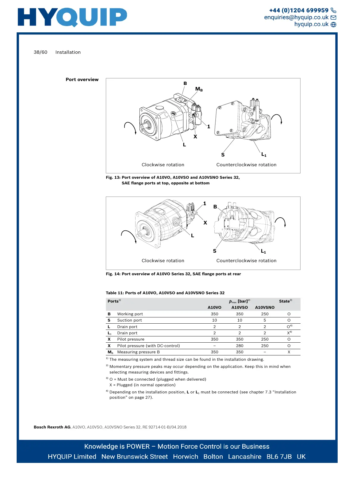
Fig. 13: Port overview of A10VO, A10VSO and A10VSNO Series 32,
SAE flange ports at top, opposite at bottom
L
L
1
B
S
1
X
Fig. 14: Port overview of A10VO Series 32, SAE flange ports at rear
Table 11: Ports of A10VO, A10VSO and A10VSNO Series 32
Ports
1)
p
max
[bar]
2)
State
3)
A10VO A10VSO A10VSNO
B Working port 350 350 250 O
S Suction port 10 10 5 O
L Drain port 2 2 2 O
4)
L
1
Drain port 2 2 2 X
4)
X Pilot pressure 350 350 250 O
X Pilot pressure (with DC-control) – 280 250 O
M
B
Measuring pressure B 350 350 – X
1)
The measuring system and thread size can be found in the installation drawing.
2)
Momentary pressure peaks may occur depending on the application. Keep this in mind when
selecting measuring devices and fittings.
3)
O = Must be connected (plugged when delivered)
X = Plugged (in normal operation)
4)
Depending on the installation position, L or L
1
must be connected (see chapter 7.3 “Installation
position” on page 27).
Port overview
Clockwise rotation Counterclockwise rotation
Clockwise rotation Counterclockwise rotation
 Loading...


