RE-A 91610/12.2015, Bosch Rexroth Corp.
Axial piston variable motor | A6VM series 71
HP – Proportional hydraulic control
11
HP2, HP6 pilot pressure increase Δp
St
= 365psi (25bar)
HP2 positive control
A pilot pressure increase of 365psi (25bar) at port X
results in an increase in displacement from V
g min
to V
g max
.
HP6 negative control
A pilot pressure increase of 365psi (25bar) at port X
results in a decrease in displacement from
V
g max
to
V
g min
.
▶ Beginning of control, setting range 75 to 725psi (5 to
50bar)
▶ Standard setting:
Beginning of control at 145psi (10bar) (end of control
at 510psi (35bar))
▼ Characteristic curve
1000 (70)
870 (60)
725 (50)
580 (40)
510 (35)
435 (30)
290 (20)
145 (10)
75 (5)
0 0.2 0.4 0.6 0.8 1.0
V
g min
V
g max
V
g
/ V
g max
HP6 HP2HP6 HP2
Beginning of
control setting
range
Displacement
Pilot pressure p
St
[psi (bar)]
Pilot
pressure
increase
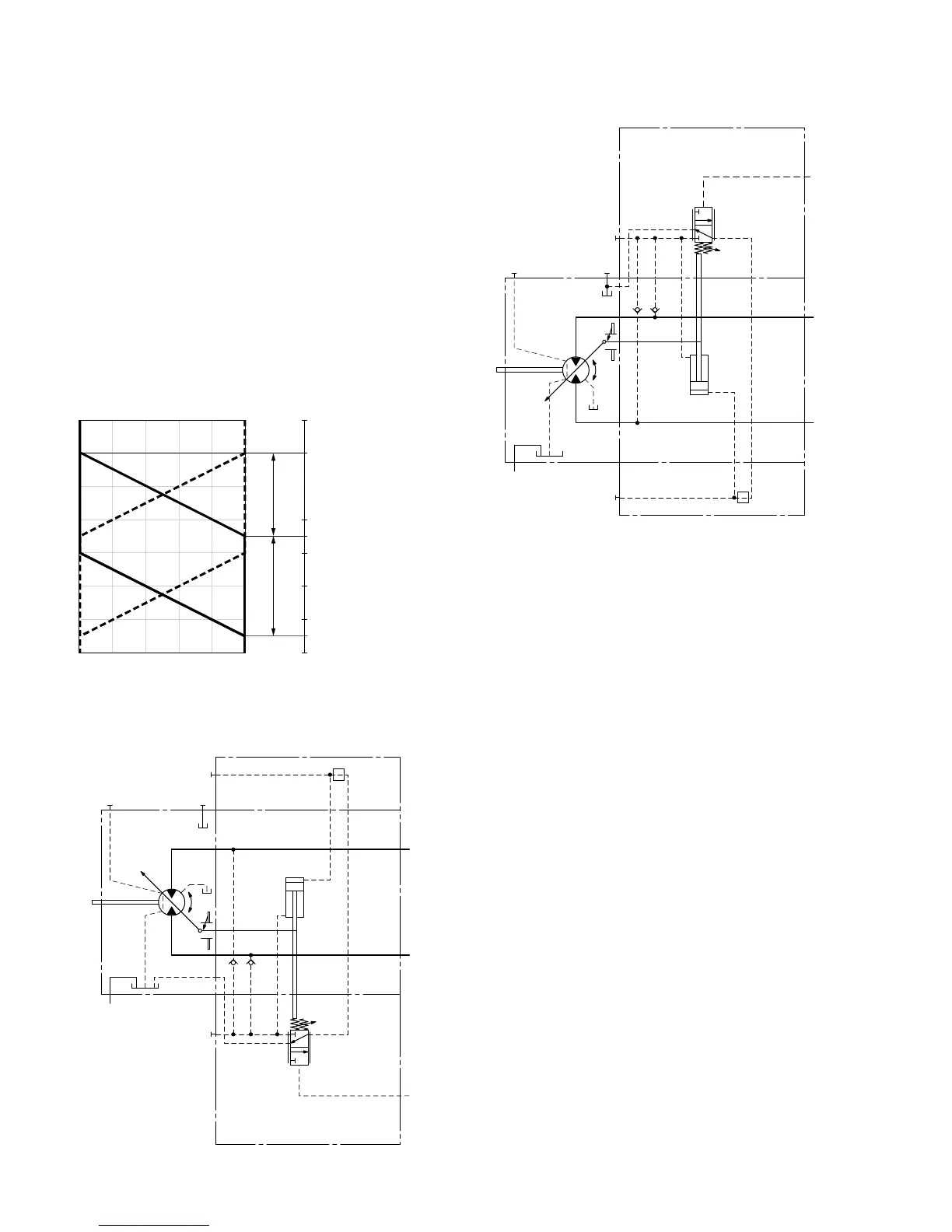
▼ Circuit diagram HP1, HP2 (positive control)
B
A
M
1
T
2
T
1
G
X
V
g min
V
g max
U
▼ Circuit diagram HP5, HP6 (negative control)
T
2
T
1
M
1
V
g min
V
g max
B
A
U
X
G

 Loading...


