Bosch Rexroth Corp., RE-A 91610/12.2015
16 A6VM series 71 | Axial piston variable motor
EZ – Two-point electric control
EZ – Two-point electric control
The two-point electric control allows the displacement to
be set to either V
g min
or V
g max
by switching the electric
current to a switching solenoid on or off.
Note
The control oil is internally taken out of the high pressure
side of the motor (A or B). For reliable control, an operat-
ing pressure of at least 435psi (30bar) is required in A
(B). If a control operation is performed at an operating
pressure <435psi (30bar), an auxiliary pressure of at least
435psi (30bar) must be applied at port G via an external
check valve. For lower pressures, please contact us.
Please note that pressures up to 7250psi (500bar) can
occur at port G.
Response time damping
The response time damping is influencing the stroke char-
acteristics of the motor and thus the reaction speed of the
machine.
Standard with Size 150 to 215
EZ5, EZ6 with throttle pin on both sides, symmetrical (as to
table)
Option with Size 60 to 115
EZ7, EZ8 (Synchronizing piston) with throttle pin on both
sides, symmetrical (as to table)
▼ Overview Throttle Pins
Size 60 85 115 150 170 215
Groove
size
[inch] 0.012 0.012 0.012 0.022 0.022 0.026
[mm] 0.30 0.30 0.30 0.55 0.55 0.65
Sizes 150 to 215
Technical data, solenoid with DIA37 EZ5 EZ6
Voltage 12V (±20%) 24V (±20%)
Position V
g max
de-energized de-energized
Position V
g min
energized energized
Nominal resistance (at 68°F (20°C)) 5.5Ω 21.7Ω
Nominal power 26.2W 26.5W
Minimum required active current 1.32A 0.67A
Duty cycle 100% 100%
Type of protection: see connector version on page 62
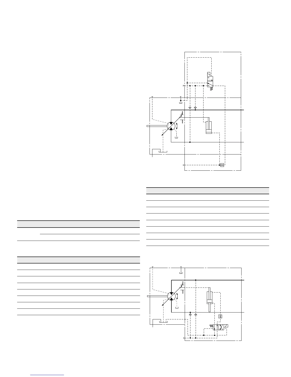
▼ Circuit diagram EZ5, EZ6 (negative control) size 150 to 215
U
T
2
T
1
M
1
V
g min
V
g max
B
A
G
Sizes 60 to 115
Technical data, solenoid with DIA45 EZ7 EZ8
Voltage 12V (±20%) 24V (±20%)
Position V
g max
de-energized de-energized
Position V
g min
energized energized
Nominal resistance (at 68°F (20°C)) 4.8Ω 19.2Ω
Nominal power 30W 30W
Minimum required active current 1.5A 0.75A
Duty cycle 100% 100%
Type of protection: see connector version on page 62
▼ Circuit diagram EZ7, EZ8 (negative control) size 60 to 115
T
1
U
T
2
G
B
A
V
g min
V
g max

 Loading...


