RE-A 91610/12.2015, Bosch Rexroth Corp.
Axial piston variable motor | A6VM series 71
Counterbalance valve BVD and BVE
65
Counterbalance valve BVD and BVE
Function
Counterbalance valves for drives and winches should
reduce the danger of overspeed and cavitation in open
circuits of axial piston motors. Cavitation occurs if, during
braking, when going downhill or during the load-lowering
process, the motor speed is greater than it should be for
the given inlet flow and thus the inlet pressure collapses.
If the inlet pressure falls below the level specified for the
relevant counterbalance valve, the counterbalance valve
piston moves into the closed position. The cross-sectional
area of the counterbalance valve return duct is then
reduced, creating a restriction in the return flow of the
hydraulic fluid. The pressure increases and brakes the
motor until the speed of the motor reaches the specified
value for the given inlet flow.
Note
▶ BVD available for sizes 60 to 215 and BVE available for
sizes 115 to 215.
▶ The BVD counterbalance valve must be ordered addi-
tionally. We recommend ordering the counterbalance
valve and the motor as a set.
Order example:A6VM085HA1T30004A/71AWV0C2
97W0-0 + BVD20F27S/41B–V03K16D0400S12
▶ For safety reasons, controls with beginning of control at
V
g
min
(e.g. HA) are not permissible for winch drives!
▶ Counterbalance valves must be optimized during proto-
type commissioning to prevent unacceptable operating
conditions and compliance with the specification must
be verified.
▶ The counterbalance valve does not replace the mechani-
cal service brake and parking brake.
▶ Observe the detailed notes on the BVD counterbalance
valve in RE 95522 and BVE counterbalance valve in
RE 95525.
▶ For the design of the brake release valve, we require the
following data for the mechanical holding brake:
– the cracking pressure
– the volume of the brake spool between minimum
stroke (brake closed) and maximum stroke (brake
released with 305psi (21bar))
– the required closing time for a warm device (oil
viscosity approx.69.6SUS (15mm
2
/s))
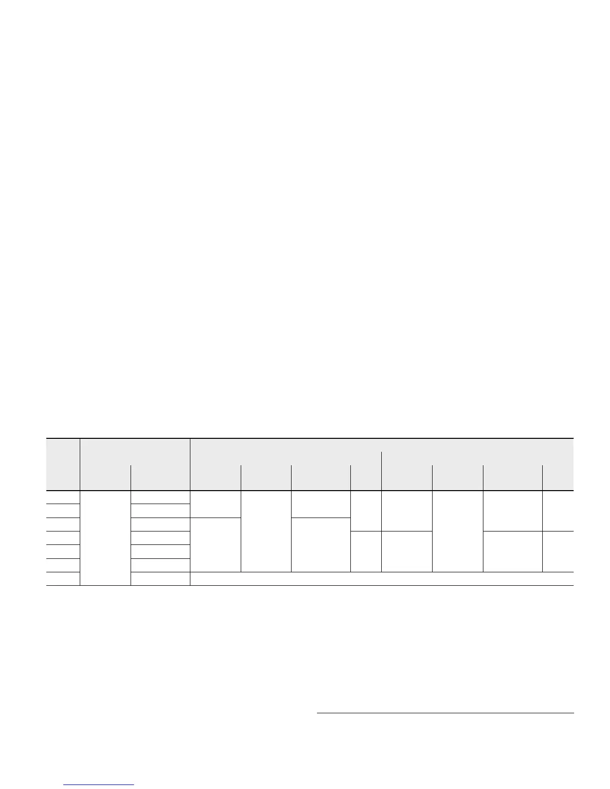
Permissible input flow or pressure when using DBV and BVD/BVE
Without valve Limited values when using DBV and BVD/BVE
Motor DBV
1)
BVD
2)
/BVE
3)
NG
p
nom
/p
max
[psi (bar)]
q
V max
[gpm (l/min)]
NG
p
nom
/p
max
[psi (bar)]
q
V
[gpm (l/min)]
Code NG
p
nom
/p
max
[psi (bar)]
q
V
[gpm (l/min)]
Code
60 6500 /7250
(450/500)
73 (276) 22 5100/6100
(350/420)
63 (240) 7 20
(BVD)
5100/6100
(350/420)
58 (220) 7W
85 88 (332)
115 108 (410) 32 106 (400)
115 108 (410) 8 25
(BVD/BVE)
85 (320) 8W
150 131 (494)
170 141 (533)
215 166 (628) On request
Mounting of the counterbalance valve
When delivered, the counterbalance valve is mounted to the
motor with two tacking screws (transport lock). The tack-
ing screws may not be removed while mounting the working
ports. If the counterbalance valve and motor are delivered
separately, the counterbalance valve must first be mounted
to the motor port plate using the provided tacking screws.
The final mounting of the counterbalance valve on the
motor is done with screw fitting of the SAE flange.
The screws to be used and the procedure mountings can be
found in the instruction manual.
1) Pressure-relief valve
2) Counterbalance valve, double-acting
3) Counterbalance valve, single-acting

 Loading...


