RE-A 91610/12.2015, Bosch Rexroth Corp.
Axial piston variable motor | A6VM series 71
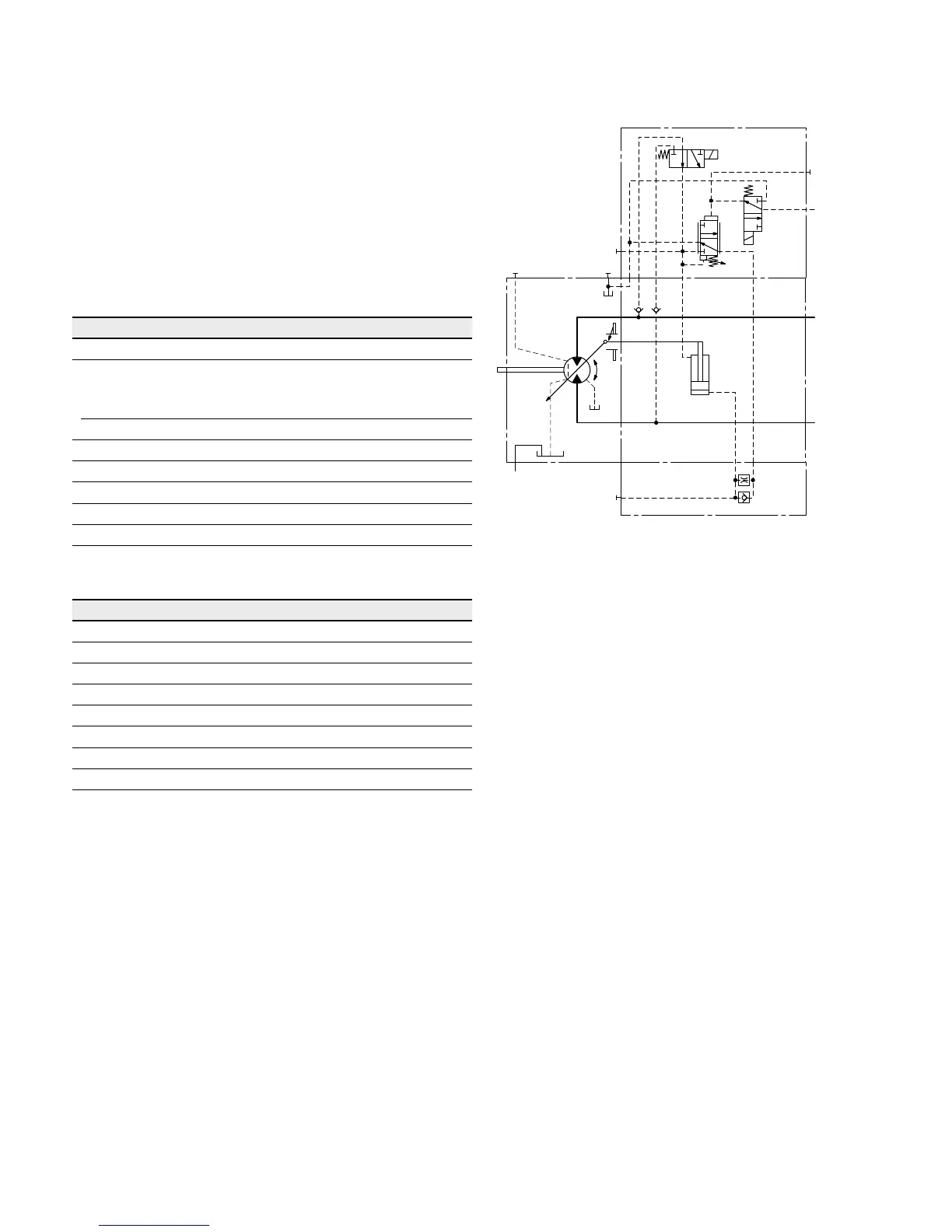
DA – Automatic speed-related control
23
DA1, DA2 electric travel direction valve + electric
V
gmax
circuit, negative control
The travel direction valve is pressure spring offset or
switched by energizing switching solenoid a, depending on
the direction of rotation (travel direction).
When the switching solenoid b is energized, the DA control
is overridden and the motor swivels to maximum displace-
ment (high torque, lower speed) (electric V
g max
-circuit).
Travel direction valve, electric
Technical data, solenoid a with DIA37 DA1 DA2
Voltage
12 V (±20 %) 24 V (±20 %)
Direction
of rotation
Operating
pressure in
ccw B de-energized de-energized
cw A energized energized
Nominal resistance (at 68°F (20°C)) 5.5Ω 21.7Ω
Nominal power 26.2 W 26.5 W
Minimum required active current 1.32 A 0.67 A
Duty cycle 100 % 100 %
Type of protection: see connector version on page 62
Electric override
Technical data, solenoid b with DIA37 DA1 DA2
Voltage 12 V (±20 %) 24 V (±20 %)
No override de-energized de-energized
Position V
g max
energized energized
Nominal resistance (at 68°F (20°C)) 5.5Ω 21.7Ω
Nominal power 26.2 W 26.5 W
Minimum required active current 1.32 A 0.67 A
Duty cycle 100 % 100 %
Type of protection: see connector version on page 62
▼ Circuit diagram DA1, DA2
T
2
T
1
M
1
V
g min
V
g max
B
A
G
X
3
a
b
X
1
U

 Loading...


