Probe Input
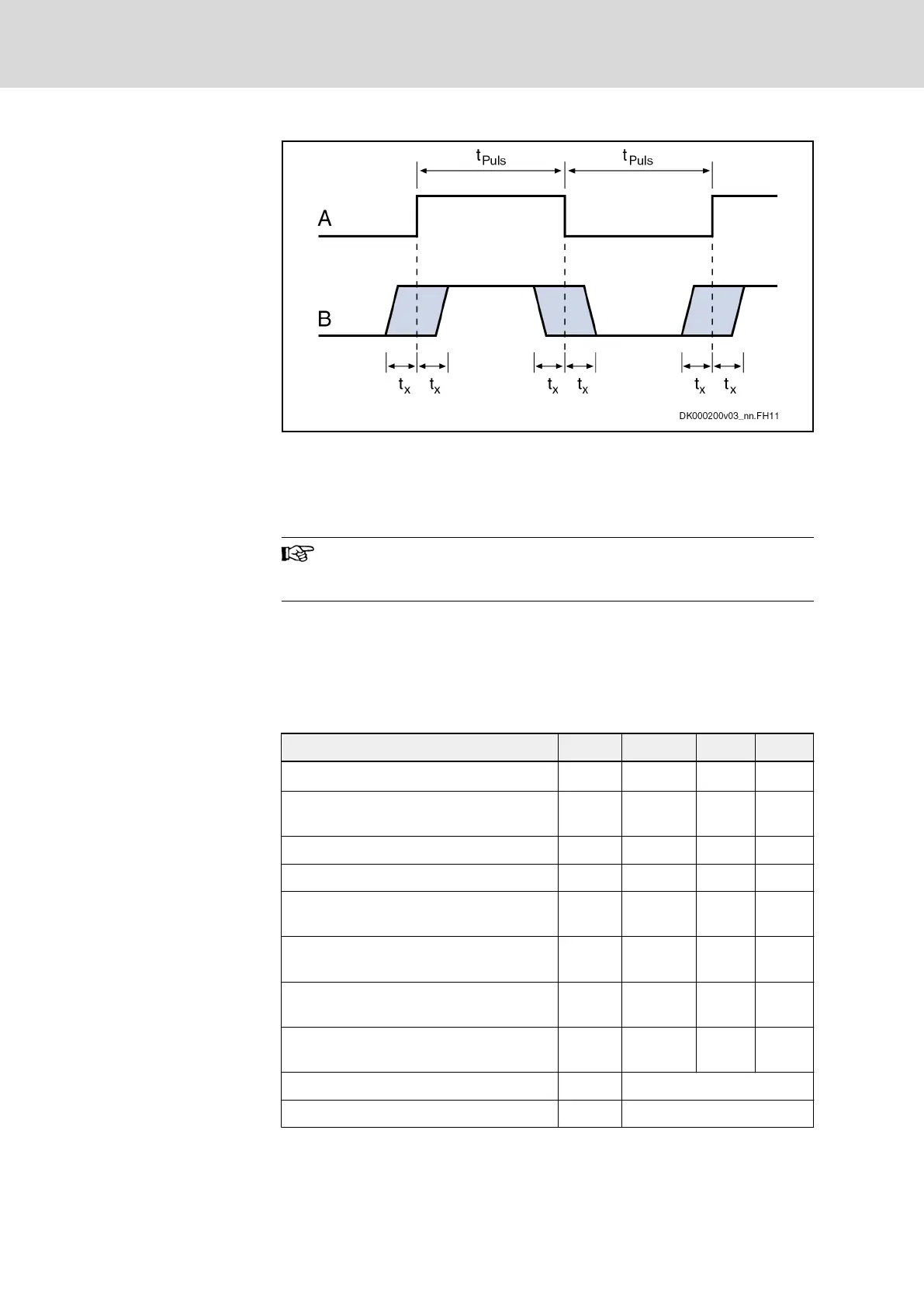
A Signal
B Signal Detection at Probe Input
t
Puls
Pulse width
t
x
Measuring accuracy of the signal edges
Fig. 12-4: Signal Detection at Probe Input
Probe inputs are inputs used to acquire fast digital input signals.
For
control
use bounce-free
switching
elements
(e.g. electronic
switches) to avoid incorrect evaluation.
External Power Supply
At
the
pins
1
and
3 of the connectors X37 and X38, you can connect an
external 24 V power supply to increase the maximum output current of the
digital outputs. The external 24 V supply must comply with a voltage
tolerance of ±20%.
Data: Outputs
Data Unit Min. Typ. Max.
Output voltage ON (with external supply) V U
ext
- 0.5 24 U
ext
Output voltage ON (without external
supply)
V 19,2 21 28,8
Output voltage OFF V n.s. n.s. 2,1
Output current OFF mA n.s. n.s. 0,05
Allowed output current per output (with
external supply)
mA n.s. n.s. 500
Allowed output current total or per group
(with external supply)
mA n.s. n.s. 1000
Allowed output current per output (without
external supply)
mA n.s. n.s. 100
Allowed output current total or per group
(without external supply)
mA n.s. n.s. 100
Update interval ns Depending on firmware
Short circuit protection Present
Bosch Rexroth AG DOK-INDRV*-SI3-**VRS**-AP06-EN-P
Rexroth IndraDrive Integrated Safety Technology "Safe Torque Off" (as of MPx-16)
130/149
Project planning
LSA Control S.L. www.lsa-control.com comercial@lsa-control.com (+34) 960 62 43 01