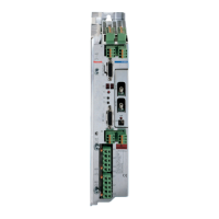
ECODRIVE DKC02.1 Drive Controller Table of contents I
DOK-ECODRV-DKC02.1****-PRJ2-EN-P
Table of contents
1 Introduction to the System 1-1
1.1 Application features.............................................................................................................................. 1-1
1.2 Overview of the functions..................................................................................................................... 1-1
2 Safety instructions for electrical drives 2-1
2.1 General ................................................................................................................................................ 2-1
2.2 Protection against contact with electrical parts.................................................................................... 2-2
2.3 Protection against shocks caused by safety extra-low voltage (SELV).........................................2-3
2.4 Protection against dangerous movements...........................................................................................2-4
2.5 Protection against magnetic and electromagnetic fields during operation and assembly ................... 2-6
2.6 Protection during handling and assembly............................................................................................ 2-7
2.7 Safe battery usage............................................................................................................................... 2-7
3 Selecting the components 3-1
3.1 Overview of the required components ................................................................................................. 3-1
3.2 Selection procedure............................................................................................................................. 3-2
3.3 Compiling the required data................................................................................................................. 3-3
4 ECODRIVE DKC drive controllers 4-1
4.1 Hardware.............................................................................................................................................. 4-1
Dimensional data and installation dimensions ..............................................................................4-1
Technical data............................................................................................................................... 4-2
Type code and rating plate............................................................................................................4-5
4.2 Firmware.............................................................................................................................................. 4-6
4.3 An overview of the electrical connections............................................................................................ 4-7
Front view with supply terminals and overall connection diagram................................................ 4-7
4.4 Electrical connections .......................................................................................................................... 4-9
Serial interface X1......................................................................................................................... 4-9
X2 external measuring system...................................................................................................... 4-9
X3 zero switch, sensor, travel limit switch, diagnostic outputs.................................................... 4-10
X4 24V control voltage supply, E-stop (emergency stop), stand-by operation............................4-11
X5 connection for motor feedback .............................................................................................. 4-13
X6 motor temperature, motor holding brake, 24V supply for the motor holding brake ............... 4-13
X7 motor power connection ........................................................................................................4-13
X8 power connection...................................................................................................................4-14
X9 DC bus connection ................................................................................................................ 4-14
X10/X11 SERCOS interface connection..................................................................................... 4-14
LSA Control S.L. www.lsa-control.com comercial@lsa-control.com (+34) 960 62 43 01

 Loading...


