EasyManua.ls Logo

Bosch SM048 User Manual

Bosch SM048
100 pages
To Next Page IconTo Next Page
Page #1 background imageLoading...
Page #1 background image
Installation, Operation and Maintenance Manual
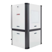
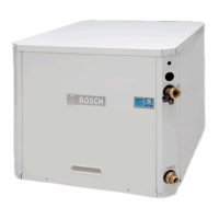
SM Series Heat pump
6 720 220 406 (2015/02)
SM024 | SM036 | SM048 | SMO60 | SM070

Table of Contents

Other manuals for Bosch SM048

Questions and Answers:

Bosch SM048 Specifications

General IconGeneral
BrandBosch
ModelSM048
CategoryHeat Pump
LanguageEnglish

Summary

Key to Symbols

Safety Warnings

General safety warnings for installation and servicing of the heat pump equipment.

Standard Package Components

List of components included in the standard package for the heat pump unit.

Warning Symbol Definitions

Defines warning symbols like NOTE, CAUTION, WARNING, and DANGER used in the manual.

Model Nomenclature

Model Number Breakdown

Detailed explanation of the model number encoding for SM Series heat pumps.

General Description

Unit Configurations and Features

Overview of SM Series heat pump configurations (VT, HZ, CF) and available factory options.

Installation Preparation

Moving and Storage Guidelines

Instructions for moving and storing the heat pump unit safely and correctly.

Configurability Options

Horizontal Configurability

Details on configuring the horizontal unit's blower orientation and required tools.

Left-Hand Unit Instructions

Step-by-step guide for reconfiguring the blower on left-hand horizontal units.

Horizontal Configurability: Blower Reorientation Steps

Blower Assembly Removal Steps

Detailed steps for removing the blower assembly from the unit.

Blower Assembly Reinstallation Steps

Detailed steps for reinstalling the blower assembly after reorientation.

Horizontal Configurability: Blower Reorientation Completion

Blower Collar and Bracket Reinstallation

Steps for reinstalling the blower collar and associated brackets.

Horizontal Configurability: Right-Hand Unit Instructions

Right-Hand Unit Panel and Motor Disconnection

Steps for removing panels and disconnecting the motor on right-hand units.

Horizontal Configurability: Right-Hand Unit Blower Steps

Blower Bracket Removal and Reinstallation

Instructions for removing and reinstalling blower brackets on right-hand units.

Blower Assembly Handling Caution

Cautionary note regarding proximity of blower to air coil and potential damage.

Horizontal Configurability: Right-Hand Unit Blower Steps Continued

Blower Assembly Sliding and Bracket Reinstallation

Steps for sliding the blower assembly and reinstalling brackets.

Horizontal Configurability: Final Steps

Panel and Bracket Reinstallation

Final steps for reinstalling panels and securing blower brackets.

Counter-Flow Configurability

Counter-Flow Unit Description

Description of the counter-flow unit's dedicated downflow configuration.

Vertical Configurability

Vertical Unit Description and Options

Description of vertical unit field configuration for various orientations and options.

Vertical Configuration Notes

Important notes on discharge air configuration and blower/panel changes.

Vertical Configurability: Discharge and Heat Options

Blower Orientation Diagrams

Diagrams illustrating top, back, and side discharge options for vertical units.

Blower and Electric Heat Compatibility

Table showing compatibility between blower orientation and electric heat.

Vertical Configurability: Steps and Tools

Vertical Unit Configuration Options Table

Table detailing required steps for various vertical unit configurations.

Accessing Internal Components

Procedure for accessing internal components by removing panels.

Required Tools for Vertical Configuration

List of tools required for vertical unit configuration tasks.

Vertical Configurability: Panel Removal Steps

Condensing Section Panel Removal

Steps for removing the condensing section access panels.

Air Handler Panel Removal and Wiring Caution

Procedure for removing the air handler panel and wiring caution.

Blower Re-Configuration Process

Reconfiguring Blower from UP to SIDE Discharge

Detailed instructions for reconfiguring the blower from UP to SIDE discharge.

Blower Motor and Assembly Removal

Steps for removing the blower motor and inlet ring assembly.

Blower Assembly Handling Caution

Caution regarding proximity of blower to air coil and potential damage.

Blower Re-Configuration: Cover and Panel Reinstallation

Blower Collar and Cover Reinstallation

Steps for removing and reinstalling the blower collar and side panel cover.

Discharge Air Configuration Note

Note that discharge air configuration change is not possible with Electric Heat Option.

Blower Re-Configuration: Bracket Reinstallation Steps

Horizontal and Vertical Bracket Reinstallation

Steps for reinstalling horizontal and vertical blower brackets in new orientations.

Blower Assembly Reinstallation Caution

Caution regarding blower housing proximity to air coil and potential damage.

Blower Re-Configuration: Final Reassembly

Blower Motor and Bracket Reinstallation

Final steps for reinstalling blower motor, inlet ring, and brackets.

Condensate Drain Connection Re-configuration

Relocating Condensate Drain Connection

Procedure for relocating condensate drain connection from front to back.

Condensate Drain Re-configuration Steps

Drain Hose and Fitting Management

Steps for cutting, routing, and reattaching the condensate drain hose.

HRP Switch Relocation

HRP Switch Wiring Instructions

Instructions for relocating the HRP Pump Disconnect Switch wiring.

Electric Heat Relocation Process

Relocating Electric Heat Components

Procedure for relocating electric heat components for servicing.

Electric Heat Element and Cover Removal

Steps for removing electric heat elements and their covers.

Electric Heat Relocation Reinstallation Steps

Electric Heat E-box and Element Reinstallation

Steps for reinstalling the electric heat E-box and elements.

Blower Collar Cover Removal

Steps for removing the blower collar cover.

Electrical Box Re-configuration Procedure

E-box Design and Access

Description of the E-box design for field configuration and servicing.

Panel Reinstallation and Duct Flanges

LCD Wiring Rerouting and Panel Reinstallation

Procedure for rerouting LCD wiring and reinstalling unit panels.

Return and Discharge Duct Flanges

Information on the return and discharge duct flanges.

Duct Flange Installation Notes

Notes on bending and installing the duct flanges.

Pre Installation Unit Preparation

Corner Cap Installation Instructions

Instructions for installing corner caps on the unit.

Identifying Corner Cap Codes and Locations

Guide to identifying corner cap identifiers and their locations.

Installing Corner Caps and Surface Preparation

Steps for installing corner caps and preparing the cabinet surface.

Unit Mounting Procedures

Mounting Vertical Units

Guidelines for mounting vertical heat pump units.

Mounting Horizontal Units

Guidelines for mounting horizontal heat pump units.

Hanging Bracket Kit Installation

Instructions for installing the hanging bracket kit on horizontal units.

Kit Components and Required Tools

List of components in the hanging bracket kit and field-provided items.

Condensate Drain Installation and Requirements

Hanging Bracket Installation Steps

Steps for installing hanging brackets and hanging the unit.

Condensate Drain Connection Requirements

Requirements for connecting and pitching the condensate drain line.

Condensate Drain Relocation Note

Note on condensate drain relocation for right-hand return conversion.

Duct System Installation Guidelines

Duct System Design and Installation Notes

Guidelines for supply and return air duct connections and insulation.

Piping Installation Guidelines

Piping Sizing and Material Recommendations

Recommendations for supply and return piping sizing and material.

Water Flow and Piping Connection Notes

Notes on water flow rates, piping connections, and valve types.

Water Quality Considerations

Water Quality Parameters

Table detailing water quality parameters for scaling, corrosion, and fouling.

Electrical Safety Warnings

Field Wiring and Code Compliance

Warnings regarding compliance with electrical codes for field wiring.

Voltage and Circuit Protection Requirements

Requirements for operating voltage and circuit protection.

Electrical Connection Procedures

Conduit Attachment and Wiring Routing

Procedures for attaching conduit and routing power supply wiring.

Power Supply for Electric Heat

Notes on separate power supplies required for units with internal electric heat.

Safety Devices and UPM Controller Overview

UPM Controller Components and Indicators

Identification of UPM controller components and status indicators.

Thermostat Connection Notes

Notes on connecting thermostats to the unit's UPM board.

Electrical Safety Controls and Sensors

Thermostat Malfunction Light Connections

Wiring procedures for thermostat malfunction light connections.

UPM Controller and Safety Controls

Overview of the UPM controller and its safety controls.

Freeze Protection Sensor Details

Details on water and evaporator side freeze protection sensors.

UPM Board Settings and Operational Features

UPM Board Default Settings and DIP Switches

Factory default settings for UPM board temperature, lockout, and alarm.

UPM Board Timers and Protection Features

Explanation of UPM board timers like ANTI-SHORT CYCLE and BROWNout protection.

Alarm and Output Signal Configuration

Configuration of alarm outputs for malfunction lights and display.

Test Mode Operation Caution

Caution regarding operation in test mode and component wear.

Freeze Sensor Operation and Alarms

Freeze Limit Trip Settings and Alarms

Details on freeze sensor settings, trip points, and alarm conditions.

Intelligent Reset and Lockout Procedures

Procedures for intelligent reset, hard lockout, and reset methods.

ECM Interface Board Functionality

ECM Interface Board Location and Function

Location and function of the ECM interface board for motor control.

Thermostat Connections and Functions

Explanation of thermostat connections and their functions on the ECM board.

ECM Interface Board Controls and Settings

CFM LED Indication and Measurement

Using CFM LED for airflow indication and measurement.

Thermostat Output Functions

Description of thermostat outputs for compressor and fan control.

Airflow Selector Operation

Airflow Adjustment and DIP Switch Settings

How to adjust airflow using the selector and DIP switches.

Dehumidification Method Selector Operation

Dehumidification Method Selection Options

Selecting between Hot Gas Reheat and fan-only dehumidification.

Constant Torque Motors (ECM) Operation

ECM Motor Description and Features

Description of ECM motor features like efficiency and fan curve.

Changing Speed Tap Instructions

Instructions for changing the speed tap on ECM motors.

Available Options Overview

Hot Gas Reheat (HGRH) Operation

Explanation of HGRH functionality, operation, and availability.

Electric Heat Functionality

Details on electric heat functionality, availability, and kW capacities.

Heat Recovery Package (HRP) Overview

Overview of the HRP option, its purpose, and major components.

Option Details and Operation

Heat Recovery Package Operation Details

Detailed operation of the HRP for heating potable water.

Heat Recovery Unit Freezing Caution

Caution regarding potential freezing damage to HRP units.

Constant Airflow Motor Functionality

Functionality of the constant airflow motor for variable airflow settings.

DPS Water Flow Proving Operation

Functionality and operation of the DPS water flow proving switch.

Pump Relay Application

Application of the factory installed pump relay for energizing pumps or valves.

Comfort Alert Module Functionality

Description and function of the Comfort Alert Module for troubleshooting.

Comfort Alert LED Indicators and Troubleshooting

Explanation of Comfort Alert LED indicators and troubleshooting guidance.

SMART START ASSIST System

Smart Start Assist Device Overview and Benefits

Overview of the SSA device, its benefits, and technology.

Smart Start Assist Specifications

Technical specifications for the Smart Start Assist device.

Smart Start Assist Mode of Operation

Mode of Operation Indicators

Explanation of the operational modes and their LED indicators.

Normal Condition Operation

Description of normal operation indicators for Smart Start Assist.

Undervoltage Condition Operation

Description of undervoltage condition indicators for Smart Start Assist.

Overcurrent Condition Operation

Description of overcurrent condition indicators for Smart Start Assist.

Incomplete Ramp Alarm Operation

Description of incomplete ramp alarm indicators for Smart Start Assist.

Smart Start Assist Operation Notes

Smart Start Assist LED Status and Recovery Alarms

Notes on LED status, recovery alarms, and time delays for SSA.

Heat Recovery Package: Water Tank Preparation

Water Tank Draining and Flushing Steps

Steps for draining and flushing the water tank before HRP installation.

HR Water Piping Installation

Instructions for installing the hot water (HR) piping for the HRP.

Heat Recovery Package: Water Tank Refill Procedure

Water Tank Refill Procedure

Steps for refilling the water tank and purging air.

Water Heater Thermostat Adjustment

Instructions for adjusting water heater thermostat settings for HRP.

Initial Start-Up Procedures

Heat Recovery System Initial Start-Up Steps

Steps for initial start-up of the heat recovery system.

Sequence of Operation

Cooling Mode Operation

Detailed sequence of operation for cooling mode.

Heating Mode Operation

Detailed sequence of operation for heating mode.

Sequence of Operation Flowchart

Cooling and Heating Mode Operation Logic

Flowchart illustrating the logic for cooling and heating modes.

Application Considerations for Water Sources

Well Water Systems

Considerations for well water systems, quality, and pressure.

Cooling Tower/Boiler Systems

Considerations for cooling tower and boiler loop systems.

Application Considerations: Piping and System Notes

Closed Loop Air Elimination and Heat Absorption

Ensuring proper operation for closed loop and heating modes.

Water Piping Exposure and Insulation Notes

Notes on water piping exposure to freezing and insulation requirements.

Piping Connections and System Flushing

Guidelines for piping connections, flushing, and valve installation.

Ball Valve Installation and Flow Balancing

Proper installation of ball valves for isolation and flow balancing.

Application Considerations: Geothermal Systems

Geothermal System Design and Installation Requirements

Requirements for specialized design and installation of geothermal systems.

Ground Loop Pumping Package (GLP) and Anti-Freeze Solutions

Use of GLP package and anti-freeze solutions for geothermal systems.

System Checkout Procedures

Pre-Energization System Checks

Checks to perform before energizing the unit after installation.

Grounding and Wiring Verification

Verification of proper grounding and electrical wiring.

Piping and Water Flow Checks

Verification of complete water piping and correct water flow.

Blower and Vibration Isolation Checks

Checks for proper blower rotation and vibration isolation.

Unit Serviceability and Panel Security

Ensuring unit is serviceable and access panels are secured.

Wiring Lead Length Considerations

Considerations for thermostat and control wiring lead lengths.

Unit Start-Up Procedures

Cooling Mode Start-Up Procedure

Steps to start up the unit in cooling mode.

System Equalization Period

Recommended time for system equalization before operation.

Heating Mode Start-Up Procedure

Steps to start up the unit in heating mode.

Routine Maintenance Procedures

Filter Maintenance Schedule

Schedule for filter changes or cleaning based on environment.

Annual System Check-up Recommendation

Recommendation for an annual check-up by a qualified mechanic.

Blower Motor Lubrication

Information on blower motor lubrication requirements.

Condensate Drain Maintenance

Procedure for checking and cleaning the condensate drain.

Periodic Lockout Causes and Troubleshooting

Common causes of periodic lockouts and troubleshooting steps.

Unit Check-Out Sheet

Customer and Unit Data Recording

Fields for customer information and unit identification.

Unit Nameplate Data Recording

Fields for recording unit nameplate data like model and refrigerant charge.

Operating Conditions Data Recording

Fields for recording operating conditions in cooling and heating modes.

Auxiliary Heat Data Recording

Fields for recording auxiliary heat data.

Support Contact Information

Contact details for technical support and information submission.

Troubleshooting Guide

UPM Board LED Error Indications

Table detailing UPM board LED colors, blinks, and error descriptions.

Troubleshooting: Unit Does Not Run

Common causes and checks for when the entire unit does not run.

Troubleshooting: Blower Operates, Compressor Does Not

Causes and checks for when the blower runs but the compressor does not.

Troubleshooting Common Issues

Troubleshooting: High Pressure Control Issues

Causes and checks for unit shutdown on high pressure control.

Troubleshooting: Low Pressure Control Issues

Causes and checks for unit shutdown on low pressure control.

Troubleshooting: Short Cycling

Causes and checks for unit short cycling issues.

Troubleshooting: Insufficient Cooling or Heating

Causes and checks for insufficient cooling or heating performance.

Compressor Specifications and Comfort Alert Codes

Compressor Ohms Specifications

Table of compressor start and run winding resistance values by model.

Comfort Alert Module - Flash Codes

Troubleshooting information for Comfort Alert Module flash codes 3, 4, and 5.

Comfort Alert Module - Flash Codes Continued

Comfort Alert Flash Codes 6, 7, 8, and 9

Troubleshooting information for Comfort Alert Module flash codes 6, 7, 8, and 9.

HRP Troubleshooting Guide

HRP Troubleshooting: Flow and Temperature Issues

Troubleshooting steps for HRP issues related to flow and water temperature.

Smart Start Assist LED Status Indication

Red LED Status Indications and Actions

Explanation of red LED status indications and corresponding actions.

Green LED Status Indications and Actions

Explanation of green LED status indications and corresponding actions.

Smart Start Assist Flashing Sequence and Recovery Mode

Understanding flashing sequences and recovery modes for SSA.

Electronic Thermostat Installation

Subbase Mounting and Wire Preparation

Steps for mounting the thermostat subbase and preparing wires.

Thermostat Connector Locations and Wiring Notes

Information on connector locations and wiring notes for different motors.

2-Cool, 3-Heat Thermostat Wiring Jumper

Instructions for connecting W1/W2 and W2/EM terminals for 2-cool, 3-heat thermostats.

Operating Temperatures and Pressures

Cooling and Heating Operating Data Table

Table showing operating temperatures and pressures for cooling and heating.

Performance Data Chart Notes

Notes and assumptions regarding the performance data chart.

Operating Temperatures and Pressures: SM036 Models

SM036 Part Load Operating Data

Operating temperatures and pressures for SM036 model at part load.

SM036 Full Load Operating Data

Operating temperatures and pressures for SM036 model at full load.

Operating Temperatures and Pressures: SM048 Models

SM048 Part Load Operating Data

Operating temperatures and pressures for SM048 model at part load.

SM048 Full Load Operating Data

Operating temperatures and pressures for SM048 model at full load.

Operating Temperatures and Pressures: SM060 Models

SM060 Part Load Operating Data

Operating temperatures and pressures for SM060 model at part load.

SM060 Full Load Operating Data

Operating temperatures and pressures for SM060 model at full load.

Operating Temperatures and Pressures: SM070 Models

SM070 Part Load Operating Data

Operating temperatures and pressures for SM070 model at part load.

SM070 Full Load Operating Data

Operating temperatures and pressures for SM070 model at full load.

Airflow Tables: Constant Torque Motors

ECM Constant Torque Motor X13 Airflow Data

Table showing airflow data for ECM Constant Torque Motor X13.

Airflow Tables: Constant Airflow Motors

ECM Constant CFM Motor EON Airflow Data

Table showing airflow data for ECM Constant CFM Motor EON.

Water Side Pressure Drop Table

Water Pressure Drop Data and Hose Kit Impact

Table showing water pressure drop and additional pressure drop from hose kits.

Wiring Diagrams: Main Unit

Main Unit Wiring Diagram (Figure #116)

Schematic diagram of the main unit's electrical wiring.

Wiring Diagram Notes

Important notes related to the main unit wiring diagram.

Wiring Diagrams: UPM and Comfort Alert

UPM and Comfort Alert Module Wiring Diagram (Figure #117)

Wiring diagram for the UPM and Comfort Alert modules.

Wiring Diagram Notes

Important notes related to the UPM and Comfort Alert wiring diagram.

Wiring Diagrams: Soft Start and ECM Motors

Soft Start Option and ECM Motor Wiring Diagram (Figure #118)

Wiring diagram for soft start option and ECM motor.

Wiring Diagram Notes

Important notes related to the soft start and ECM motor wiring diagram.

Wiring Diagrams: ECM Motor Control

ECM Motor Control Wiring Diagram (Figure #119)

Wiring diagram for ECM motor control connections.

Wiring Diagram Notes

Important notes related to the ECM motor control wiring diagram.

Wiring Diagrams: Thermostat and ECM Connections

Thermostat and ECM Motor Wiring Diagram (Figure #120)

Wiring diagram showing thermostat and ECM motor connections.

Wiring Diagram Notes

Important notes related to thermostat and ECM motor wiring.

Wiring Diagrams: Electric Heat Integration

Electric Heater Wiring Diagram (Figure #121)

Wiring diagram for the electric heater package.

Wiring Diagram Notes

Important notes related to the electric heater wiring diagram.

Wiring Harness Drawings

Constant Torque Motor Wiring Harness

Diagrams for constant torque motor wiring harnesses.

Constant Torque Motor Harness Diagram (Figure #123)

Detailed harness diagram for constant torque motors.

Wiring Harness Drawings: Constant Airflow Motor

Constant Airflow Motor Harness Diagram (Figure #124)

Diagram showing wiring harness connections for constant airflow motors.

Spare Parts List: Vertical Configuration

Vertical (VT) Configuration Parts List

List of spare parts for the Vertical (VT) configuration.

Vertical Parts List Table

Detailed table of VT configuration parts with part numbers.

Vertical Configuration Parts List Continued

Vertical Parts List Table Continued

Continuation of the spare parts list table for VT configuration.

Vertical Parts List: Cabinet Components

Figure #125: VT Cabinet Exploded View

Exploded view diagram of VT unit cabinet components.

Vertical Parts List: Blower Assembly

Figure #126: VT Blower Exploded View

Exploded view diagram of VT unit blower assembly components.

Vertical Parts List: Refrigeration and Electrical Components

Figure #127: VT Refrigeration and Electrical Exploded View

Exploded view of VT unit refrigeration and electrical components.

Vertical Parts List: Detailed Cabinet Views

Figure #128: VT Detailed Cabinet Parts Views

Detailed views of specific VT unit cabinet parts.

Vertical Parts List: Detailed Electrical Views

Figure #129: VT Detailed Electrical and Refrigeration Views

Detailed views of VT unit electrical and refrigeration components.

Spare Parts List: Horizontal Configuration

Horizontal (HZ) Configuration Parts List

List of spare parts for the Horizontal (HZ) configuration.

Horizontal Parts List Table

Detailed table of HZ configuration parts with part numbers.

Horizontal Configuration Parts List Continued

Horizontal Parts List Table Continued

Continuation of the spare parts list table for HZ configuration.

Horizontal Parts List: Cabinet Components

Figure #130: HZ Cabinet Exploded View

Exploded view diagram of HZ unit cabinet components.

Horizontal Parts List: Blower Assembly

Figure #131: HZ Blower Exploded View

Exploded view diagram of HZ unit blower assembly components.

Horizontal Parts List: Refrigeration Components

Figure #132: HZ Refrigeration Exploded View

Exploded view of HZ unit refrigeration components.

Horizontal Parts List: Panel Components

Figure #133: HZ Panel Exploded Views

Exploded view diagrams of HZ unit panel components.

Horizontal Parts List: Detailed Electrical Views

Figure #134: HZ Detailed Electrical Views

Detailed views of HZ unit electrical components.

Spare Parts List: Counter Flow Configuration

Counter Flow Configuration Parts List

List of spare parts for the Counter Flow configuration.

Counter Flow Parts List Table

Detailed table of Counter Flow configuration parts with part numbers.

Counter Flow Configuration Parts List Continued

Counter Flow Parts List Table Continued

Continuation of the spare parts list table for Counter Flow configuration.

Counter Flow Part List: Cabinet Components

Figure #135: CF Cabinet Exploded View

Exploded view diagram of Counter Flow unit cabinet components.

Counter Flow Part List: Blower Assembly

Figure #136: CF Blower Exploded View

Exploded view diagram of Counter Flow unit blower assembly components.

Counter Flow Part List: Panel Components

Figure #137: CF Panel Exploded Views

Exploded view diagrams of Counter Flow unit panel components.

Counter Flow Part List: Refrigeration Components

Figure #138: CF Refrigeration Exploded View

Exploded view of Counter Flow unit refrigeration components.

Dimensional Drawings: Horizontal End Blow

Horizontal End Blow Dimensions (Figure #140)

Diagram and table showing dimensions for horizontal end blow units.

Horizontal End Blow Dimensions Table

Table listing dimensions for horizontal end blow configurations.

Dimensional Drawings: Horizontal Straight Through

Horizontal Straight Through Dimensions (Figure #141)

Diagram and table showing dimensions for horizontal straight through units.

Horizontal Straight Through Dimensions Table

Table listing dimensions for horizontal straight through configurations.

Dimensional Drawings: Horizontal Hanging Bracket Location

Horizontal Hanging Bracket Locations (Figure #142)

Diagram and table showing hanging bracket locations for horizontal units.

Horizontal Hanging Bracket Locations Table

Table listing hanging bracket location specifications.

Dimensional Drawings: Counter Flow Configuration

Counter Flow Dimensions (Figure #143)

Diagram and table showing dimensions for counter flow units.

Counter Flow Dimensions Table

Table listing dimensions for counter flow configurations.

Dimensional Drawings: CF-Vertical Configuration

CF-Vertical Dimensions (Figure #144)

Diagram and table showing dimensions for CF-Vertical units.

CF-Vertical Dimensions Table

Table listing dimensions for CF-Vertical configurations.

Related product manuals