Installation
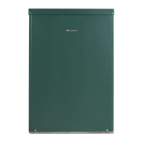
Greenstar Danesmoor External
ErP+
and External System
ErP+
6720821725 (2018/04) 23
Fig. 32 Condensate
[P] Condensate collection sump
[R] Manifold access cover
[S] Screws
Fire valve
Where required, check that the oil supply pipe has a fire valve fitted
externally to the building with the fire valve sensor located within the
appliance case.
A fire valve sensor clip [1] is provided for this purpose on the support
bar between the side panels.
Fig. 33 Fire valve clip
[1] Fire valve clip
[2] Fire valve label
The fire valve label [2] states that the fire valve should be rated at 85°C
or above to avoid nuisance cut outs.
5.7 Oil burner and pump
Oil burner nozzle
Before removing or fitting a new nozzle refer to figure 34:
▶ Remove the screws [1] from the blast tube [2] and remove the blast
tube
▶ Unplug the HT leads [4]
▶ Loosen the screw [3] securing the break plate[5] and slide the unit
off
▶ Use a suitable spanner to stop the nozzle body turning
▶ Remove the nozzle [8]and secure the new nozzle, hand tight
▶ Tighten the nozzle utilising the two spanners used during removal, do
not overtighten
▶ Refit the break plate ensuring that the photocell and the break plate
hole [5] are aligned and secure with the screw [3] into the seating
provided [7]
▶ Reconnect the HT leads [4]
▶ Refit the blast tube [2] and secure with the screws [1]
Fig. 34 Nozzle access
500ml
6720808218-37.1Wo
S
R
P
CAUTION: MAINS SUPPLIES
▶ Isolate the oil & water mains supply before starting
any work and observe all relevant safety precautions.
NOTICE: Nozzle orifice contamination
▶ to avoid contamination do not dismantle, clean or
touch the nozzle tip
There is a recirculation tube fitted to the 12/18 models,
this does not need to be removed from the blast tube
6720821683-12.1Wo
8
6
4
3
5
7
2
1

 Loading...


