Installation
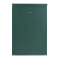
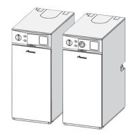
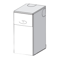
Greenstar Danesmoor External
ErP+
and External System
ErP+
6720821725 (2018/04) 27
System appliance electrical connections.
Fig. 42 System wiring diagram
Key to components:
[1] Remote junction box (10 way).
[2] Air pressure switch
[3] High limit thermostat
[4] Frost thermostat
[5] Earth stud
[6] Terminal connector block
[7] Control thermostat
[8] Flue manual reset overheat thermostat
[9] Boiler manual reset overheat thermostat
[10] Demand neon
[11] Burner socket
[12] Mode switch
[13] Service socket connection
[14] Burner plug
[15] Burner control box
[16] Pump
6720809437-23.2Wo
3
4
2
2LN 31
2
3
4
5
7
8
9
10
13
12
11
6
NL
Control Box
Green/Yellow
Green/Yellow
Grey
Grey
Brown
Brown
Blue
Red
16
L
N
L3 N L2 L1
14
15
M
LN
Riello Burner Control Box
Green/Yellow
Grey
Red
Black
L3 N L2 L1
1
Junction Box/Wiring Centre

 Loading...


