61
2.7 Protection Mechanism Summary
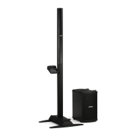
L1
®
Model II Cylindrical Radiator
®
Loudspeaker
The L1 Cylindrical Radiator speaker array consists of two sections, an upper and lower section,
with 12 drivers each for a total of 24 drivers. The lower array section plugs directly into the cavity
in the center of the L1 Model II power stand. Electrical connections are made via Molex connec-
tors in the power stand and the bottom of the lower array section. The upper section of the line
array plugs directly into the top of the bottom section, aligned by a bayonet pin. Electrical con-
nection is made by another Molex connector to the top of the lower array section. The result is
that there are no cables needed to connect the line array sections to the power stand.
There is no crossover or protection circuitry in either section of the line array. All protection and
EQ is performed in the power stand. The drivers of both sections are replaceable, as are the
grilles and the Bose
®
logo.
Theory of Operation
Fault Detection What shuts
down
Indicator
Output
Recovery when
fault is removed
Notes Fault
LED
Input Signal
Level
Clipping
Output signal level re:
0.865 of amplifier DC
supply
Per channel None Immediate Detection
threshold tied to
DC over/under
voltage threshold
NO
Output
Signal
Current
Limit
Output MOSFET 'on'
voltage
Per MOSFET None Immediate FET is shut off for
short time (1.25
usec) then
restored causing
"self-oscillation"
NO
Output
Over-current
/O.C. (short
circuit,
saturation)
Detects output
current limit over a
settable time
constant
Per channel OC Time settable by
resistor value
Time constants
shared with Zobel
protection
RED
Zobel
Protection
Over-voltage across
Zobel resistor
Shutdown
per channel
OC Time settable by
resistor value
Shared time
constant with OC
RED
Thermal
External Negative
Temperature
Coefficient resistor -
threshold detection
with hysteresis
Both
amplifiers
TH System turns
back on when
NTC when
voltage above
threshold
(depends on
thermal constant
of system)
One NTC resistor
per system - will
be two
RED
Amp DC
voltage
over/under
Percentage of
amplifier DC supply
voltage (typically
135%). Under voltage
detection optional to
insure controlled
startup.
Both
amplifiers
EN Capacitors are
given a discharge
path to prevent
long recovery
time - but enable
circuit has long
recovery
Detection
threshold tied to
input signal
clipping threshold
NO
Control
Voltage
(5 Vdc) DC
over / under
Percentage of 5V
voltage
Both
amplifiers
EN Immediate NO
Converter
Over-current System None Immediate NO
Converter
Thermal System None Depends on
thermal constant
of system
NO
 Loading...