37
DISASSEMBLY PROCEDURE
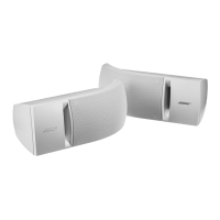
Figbure 15. Volume Board Screws Removal
4. Volume Board Removal
6.1 Perform step 1.
6.2 Remove the 4 screws that secure the
Volume board as indicated in Figure 15.
6.3 Push the 3 Volume buttons out and lift o
the board.
L1 Pro32 Upper Mid-high Array Procedures
1. Grille Removal
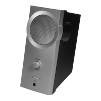
1.1 Remove the 8 screws that secure the
Endcaps from both ends of the Upper Array as
indicated in Figure 16.
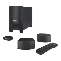
1.2 Lift o both endcaps. Figure 17.
Note: Be careful the cable of one of endcaps
is very short.
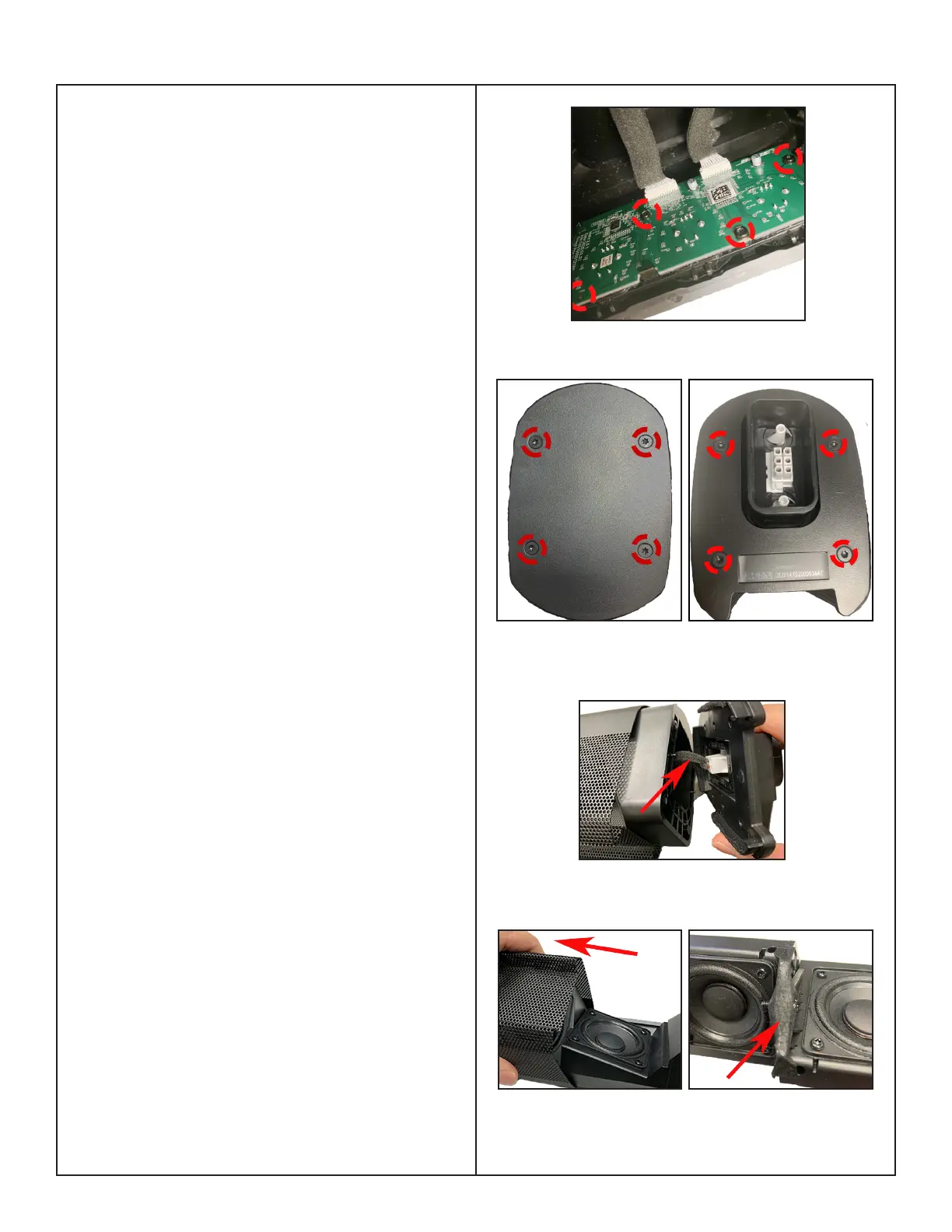
1.3 Grasp the Grille and carefully slide the
grille o of the bae. Figure18 (left).
Re-assembly Note: Be sure there is sucient
gasket material on the Grille to prevent buzzes
as the red arrow indicated in Figure18 (right).
Gasket material PN: 843112-0101
Perform the Array sweep tests after replacing
the Grille.
Figure 16. Both Ends of Endcaps Screws
Removal
Figure 17. One Endcap Removal
Figure 18. Array Grille Removal & Gasket
Material Location

 Loading...