Panel Descriptions
5
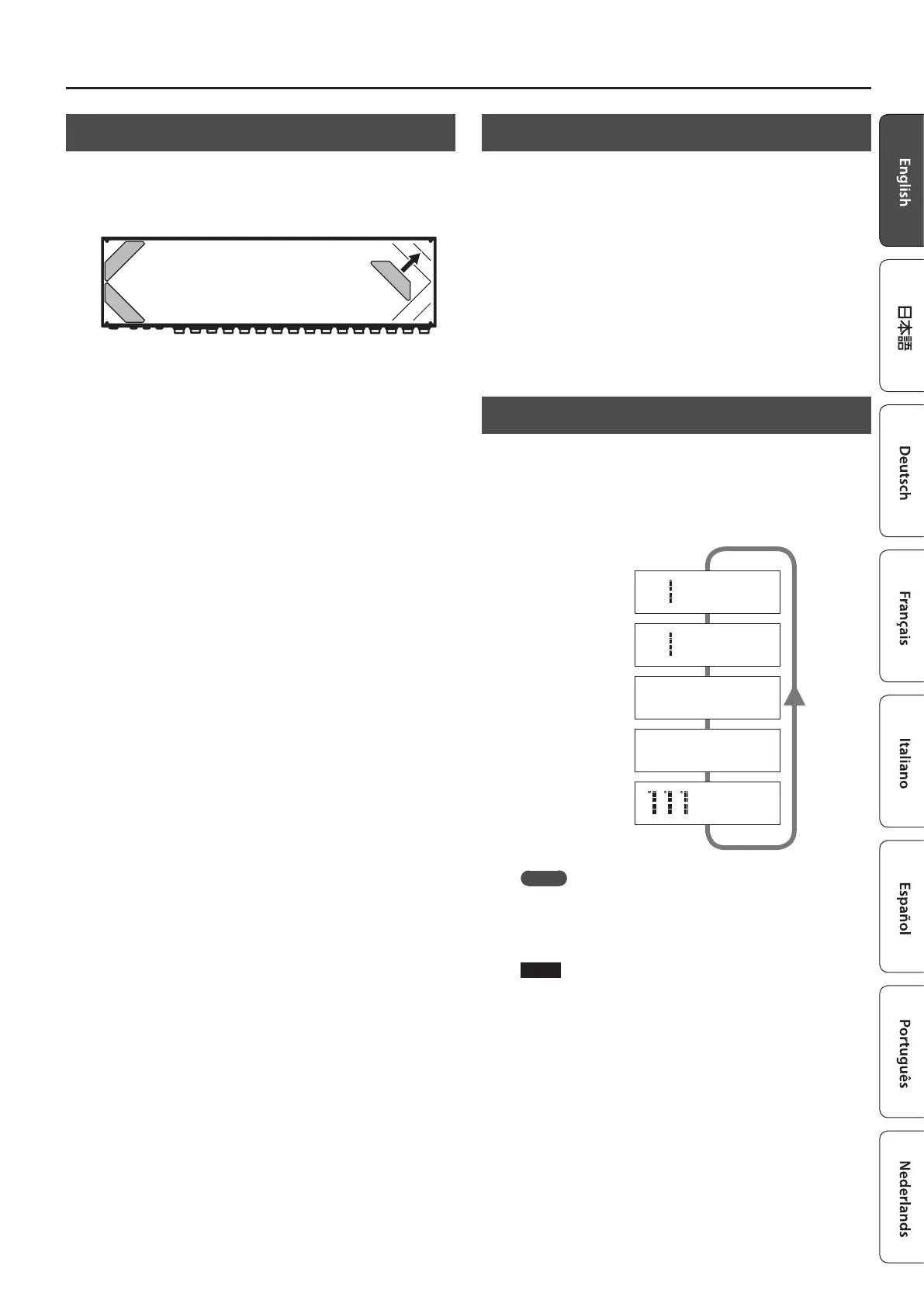
Attaching the Rubber Feet
You can attach the rubber feet (included) if necessary.
Attach the rubber feet in alignment with the marks on the bottom
of the unit.
* When turning the unit over, be careful so as to protect the buttons
and switches from damage. Also, handle the unit carefully; do not
drop it.
* If the rubber feet are not attached correctly, the unit may be
deformed when you press the switches.
Turning the Power On and O
Once everything is properly connected (p. 2), be sure to follow the
procedure below to turn on their power. If you turn on equipment in
the wrong order, you risk causing malfunction or equipment failure.
When powering up: Turn on the power to your guitar amp
last.
When powering down: Turn o the power to your guitar amp
rst.
Switching the Play Screen
The screen that appears when you turn on the power is called the
“play screen,” and the state in which the play screen is shown is
called “play mode.”
There are ve types of play screen as shown in the following
illustration, and you can use the [DISPLAY/EXIT] button to switch
between them.
Patch name screen
Master BPM
&
CTL out screen
Patch number screen
Loop structure screen
Loop On/O screen
111 BOSS ES-5
Ì=120
O-5-4-3-2-1-I _
111 BOSS ES-5
5 * 3 * 1
_
C1 |C2 |C3 |C4
ON|OFF| Ì |120 _
BOSS ES-5
Ì=120
_
MEMO
Even in play mode, you can use the [
K
] [
J
] buttons and [–] [+]
buttons to edit the settings.
To save your edited settings, use the patch write (p. 6) operation.
NOTE
The explanations in this manual include illustrations that depict
what should typically be shown by the display. Note, however,
that your unit may incorporate a newer, enhanced version of the
system (e.g., includes newer sounds), so what you actually see in
the display may not always match what appears in the manual.