Eects/Patch Settings
12
Example setting
When a specic patch is selected, use the expression pedal to control the
volume of the modeling
Select the patch whose settings you want to edit, then make the following
parameter settings.
Button Parameter Value
[SYSTEM] SysCtl: EXP1on Fnc PATCH SETTING
[EFFECTS] Ctl: EXP1on Func MODELING VOL
Assign Settings (Asgn 1–8: )
For each parameter, you can specify, in detail, which controller will control which parameter.
You can use Assign 1–8 to make eight dierent sets of settings.
* This is available if the Sys: Controller (p. 13) is set to “PATCH SETTING.”
Parameter Explanation
On/O Turns Assign 1–8 on/o.
Target
Selects the parameter that will be controlled. For details on the parameters,
refer to the explanations of each parameter in this manual.
Target Min
Target Max
Species the range of change for the parameter. The values will depend on
the parameter that’s assigned by Target.
Source
Selects the controller to which the function will be assigned.
CTL 1–CTL 4
[CTL 1] [CTL 2] pedals of this unit and external footswitch
(CTL 3, CTL 4)
GK S1,
GK S2
[S1] [S2] buttons of the GK pickup
GK VOL Volume knob of the GK pickup
EXP1 SW Expression pedal switch
EXP1 ON Expression pedal when the expression pedal switch is on
EXP1 OFF Expression pedal when the expression pedal switch is o
EXP2 External expression pedal
INT PDL
Internal pedal
The virtual expression pedal will begin
operating when started by the specied
trigger (Int Pedal Trig), modifying the
parameter specied by “Target.”
For details on the parameters that can be assigned to the
internal pedal, refer to “Int Pedal Time” and “Int Pedal Curve.”
WAVE PDL
Wave pedal
The virtual expression pedal will cyclically modify the
parameter specied by “Target” in a xed wave form.
CC#1–31,
CC#64–95
Control change number from an external MIDI device
Src Mode
MOMENTARY
The value will normally be o (minimum value), and will
be on (maximum value) only while the control is being
operated.
* If you want to use the internal pedal or wave pedal, set
to “MOMENTARY.”
TOGGLE
The value will toggle between o (minimum) and on
(maximum) each time the control is operated.
S. Range Min
S. Range Max
Within the operating range of the source, this species the range that will
control the target parameter.
The target parameter will be controlled within the range specied. Normally,
you should leave Range Min at “0” and Range Max at “127.”
Int Pdl Trig *1
Species how the motion of the internal pedal will be triggered.
PATCH
CHANGE
Triggered when you switch patches.
CTL 1–4 Triggered when you operate the [CTL] pedal.
EXP1 SW Triggered when you operate the expression pedal switch.
EXP1 OFF LOW
Triggered when you move the expression pedal to
minimum.
EXP1 OFF MID
Triggered when you depress the expression pedal through
the center value.
EXP1 OFF HI
Triggered when you move the expression pedal to
maximum.
EXP1 ON LOW
Triggered when you move the expression pedal to
minimum while the expression pedal switch is on.
EXP1 ON MID
Triggered when you depress the expression pedal through
the center value while the expression pedal switch is on.
EXP1 ON HI
Triggered when you move the expression pedal to
maximum while the expression pedal switch is on.
EXP2 Triggered when you move the external expression pedal.
GK S1
GK S2
Triggered when you operate the [S1]/[S2] button of the GK
pickup.
Int Pdl Time *1
Species the time over which the internal pedal will move from the released
(heel) position to the depressed (toe) position.
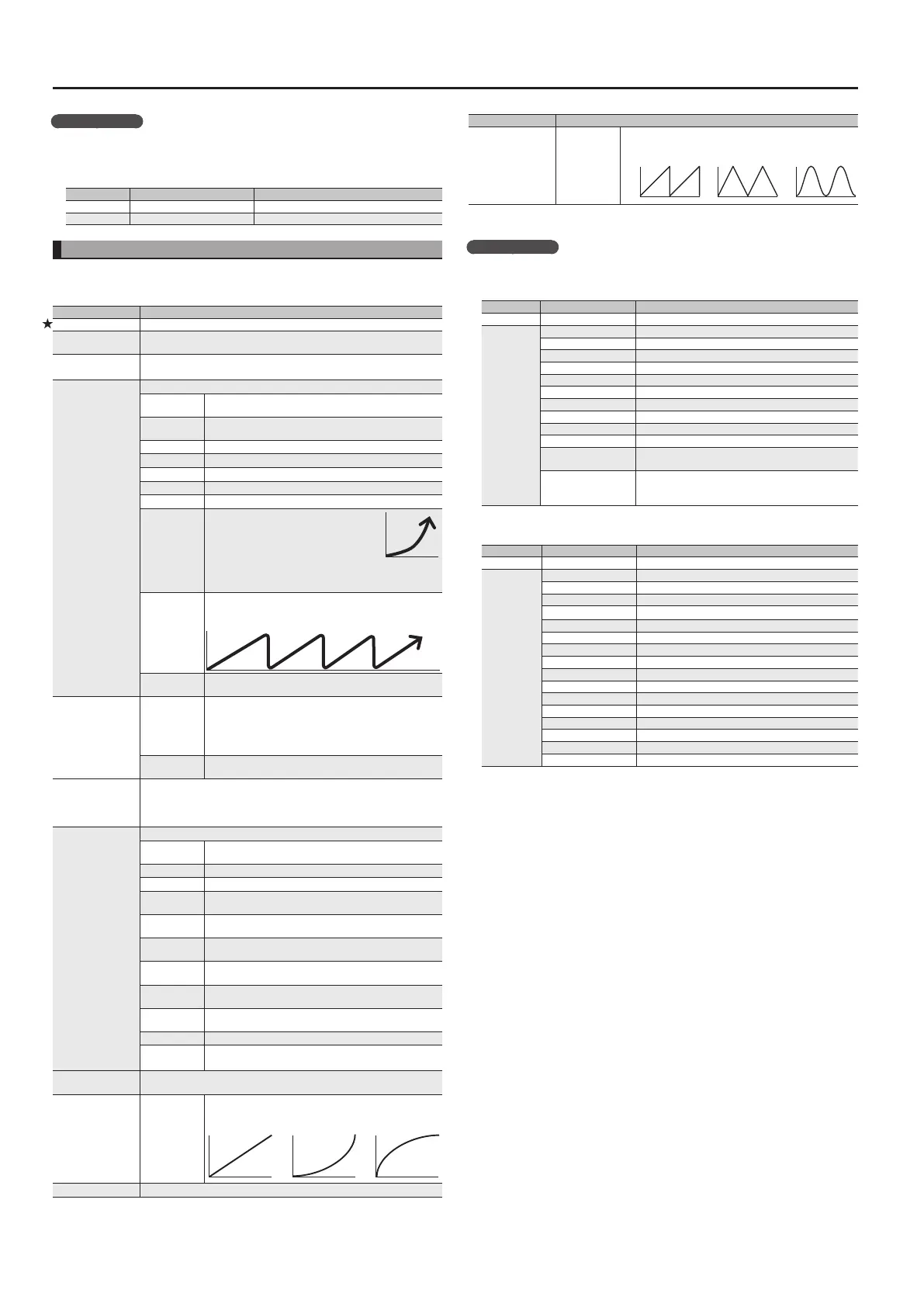
Int Pdl Curve *1
LINEAR,
SLOW RISE,
FAST RISE
Select one of the following curves to specify the change
produced by the internal pedal.
LINEAR SLOW RISE FAST RISE
Wav Pdl Rate *2 Species the time for one cycle of the wave pedal.
Parameter Explanation
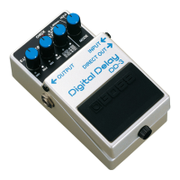
WPdWavFrm *2 SAW, TRI, SIN
Select one of the following to specify the change produced
by the wave pedal.
SAW
TRIANGLE
SINE
*1 Source=INT PDL only
*2 Source=WAVE PDL only
Example setting
Make smoothly bend up one octave when you press the [CTL 1] pedal
Select the patch whose settings you want to edit, and then make the following
parameter settings.
Button Parameter Value
[SYSTEM] SysCtl: CTL1 Func PATCH SETTING
[EFFECTS]
Fx: Type PEDAL BEND
Asgn1: On/O ON
Asgn1: Target FXP.BND: POSITION
Asgn1: Target Min 0
Asgn1: Target Max 100
Asgn1: Source INT PDL
Asgn1: Src Mode MOMENTARY
Asgn1: S. Range Min 0
Asgn1: S. Range Max 127
Asgn1: Int Pdl Trig CTL 1
Asgn1: Int Pdl Time
20
(Adjust the time over which the pitch rises an octave.)
Asgn1: Int Pdl Curve
LINEAR
(You can select a dierent curve to modify the way in
which the change occurs.)
For guitar solos, you want to be able to step on the [CTL 1] pedal to switch
AMP to solo mode
Button Parameter Value
[SYSTEM] Sys: CTL 1 Func PATCH SETTING
[EFFECTS]
Asgn1: On/O ON
Asgn1: Target AMP: SOLO SW
Asgn1: Target Min OFF
Asgn1: Target Max ON
Asgn1: Source CTL 1
Asgn1: Src Mode TOGGLE
Asgn1: S. Range Min 0
Asgn1: S. Range Max 127
Asgn2: On/O ON
Asgn2: Target AMP: GAIN SW
Asgn2: Target Min LOW
Asgn2: Target Max MID
Asgn2: Source CTL 1
Asgn2: Src Mode TOGGLE
Asgn2: S. Range Min 0
Asgn2: S. Range Max 127
 Loading...