110
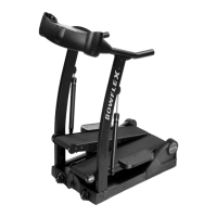
6. Using a 5mm hex wrench, remove the four screws (indicated by oval) from the
Static Handlebar Assembly.
7. Carefully lift the Static Handlebar Assembly and expose the Cable Connec-
tions.
Note: Do not crimp any of the Console Cables. This step may require two
people.
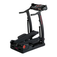
8. Carefully disconnect the Cables while not allowing them to fall into the Console
Mast.
Note: Do not crimp any of the Console Cables.
9.Toprotectthepaintandnishesfromscratches,gentlyplaceallpartsona
towel or piece of cardboard before attempting to replace any Cable(s).
10.FromthetopoftheStaticHandlebarAssembly,thereare4Cables:
Upper Body Sensor Cable(3-pin,atconnector)
To replace, go to the next Step.
Input/Output (I/O) Cable(14-pin,two-rowconnector)
To replace, go to the next Step.
Resistance Knob Cable(5-pin,atconnector)
Toreplace,gotoStep14.
Contact Heart Rate Cable(4-pin,atconnector)
The Contact Heart Rate Cable is not available for replacement.
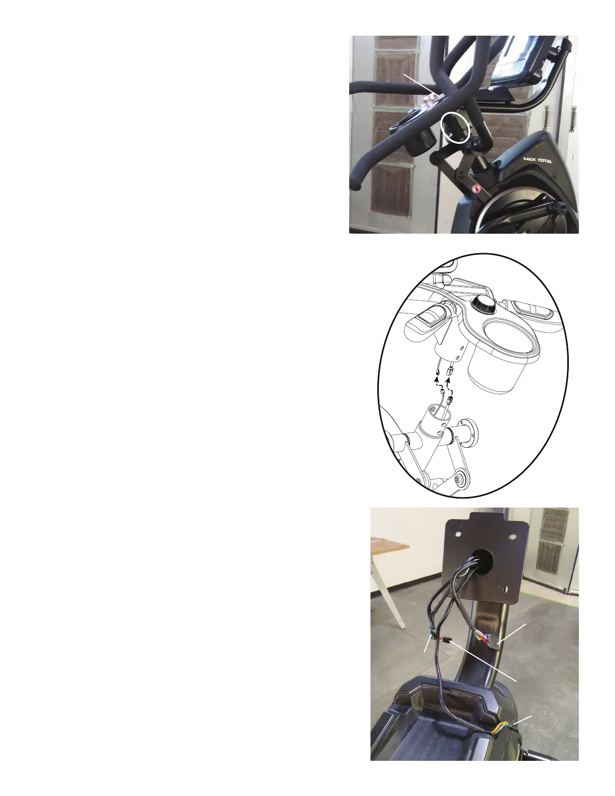
Static Handlebar
Assembly
Input/Output
(I/O) Cable
Upper Body
Sensor Cable
Resistance
Knob Cable
Contact Heart
Rate Cable