143
Cap
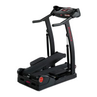
10.Usinga#2Phillipsscrewdriver,removetheindicatedscrew(byarrow)
from the Rear Shroud.
11. Carefully remove the Rear Shroud from the machine. Place a standard
screwdriver behind and near the middle of the Rear Shroud and gently pry
until it releases. Then move the screwdriver to the bottom and gently pry
until the Rear Shroud comes off.
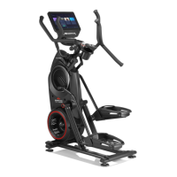
12. Using a 5mm hex wrench, remove the hardware (indicated by ovals)
from the Right Upper Handlebar.
Note: Be aware that the Upper Handlebar must be supported when
removing the hardware.
13. Place a rag or protective material below the Right Connector Arm to
protect the Shrouds from potential scratches from the Right Connector
Arm.
14.Usinga6mmhexwrench,removethehardwarethatconnectsthe
Right Connector Arm to the Right Pivot Arm (indicated by arrow).
Note: The Connector Arm will pivot downward if not lowered slowly onto
the rag protecting the Shroud.
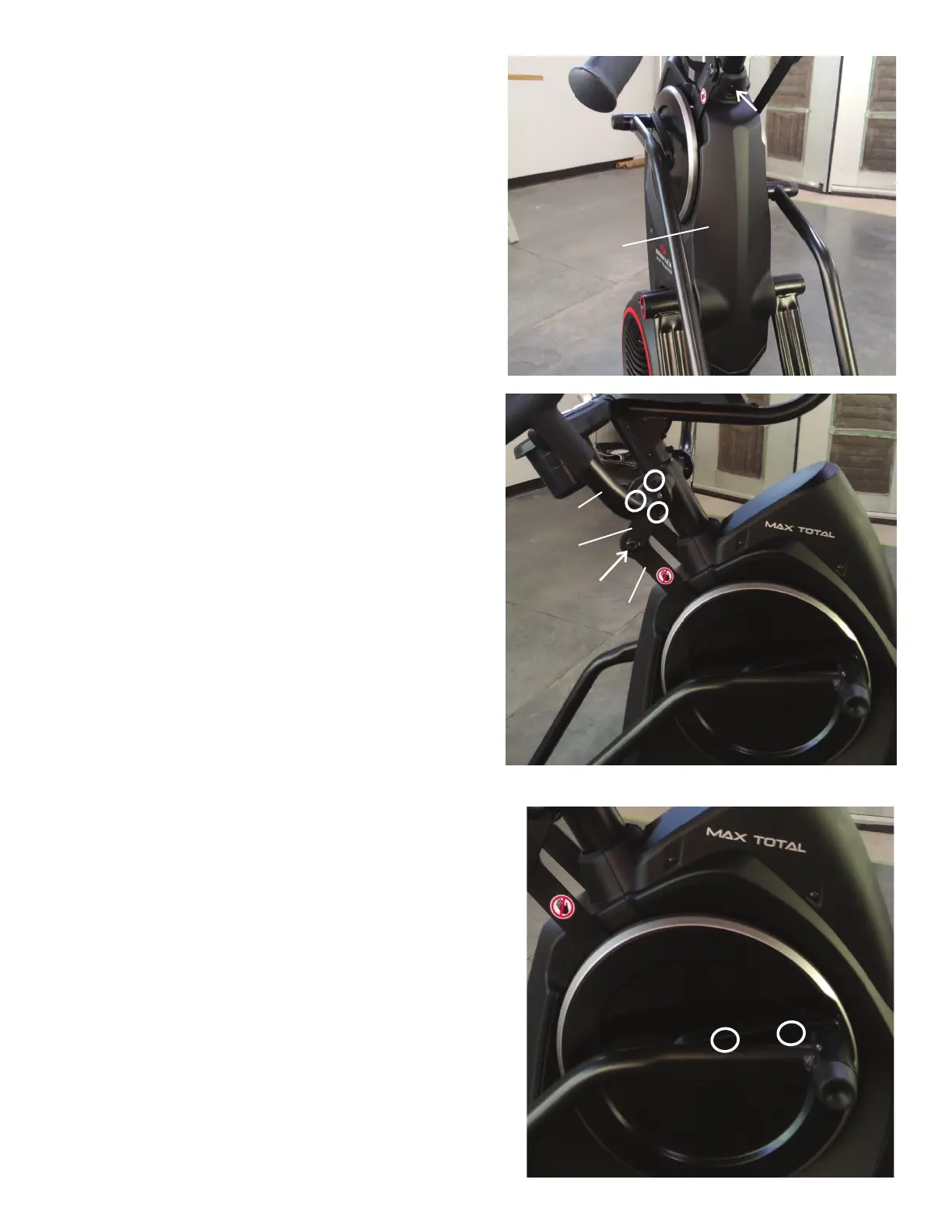
15.Usinga#2Phillipsscrewdriver,removethe2indicatedscrewsfrom
the Right Crank Cover.
Note: The Crank Cover screws may have been over-tightened when
installed. Try not to strip the screws when removing them.
16. Remove the Right Crank Cover from the machine.
Rear Shroud
Right Upper
Handlebar
Pivot Arm
Right Connector
Arm
Right Crank Cover