54
Note: Your machine may not match the images provided exactly.
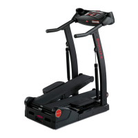
1. Remove the indicated Cap from the left side of the machine.
2. Using a 6mm hex wrench, remove the hardware exposed from below
the Cap.
3. Lift the Foot Pedal and slide the Leg Assembly straight off the ma-
chine.Besuretopullstraightout,ortheLegAssemblymaybedifcultto
remove.
4.RemovetheWaveWasherfromtheCrankArm,andplaceitinasecure
location for re-use.
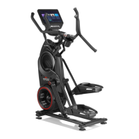
5. Using a 5mm hex wrench, remove the indicated hardware from the Left
Upper Handlebar and place it out of the work area.
Note: Be aware that the Left Upper Handlebar must be supported when
removing the hardware.
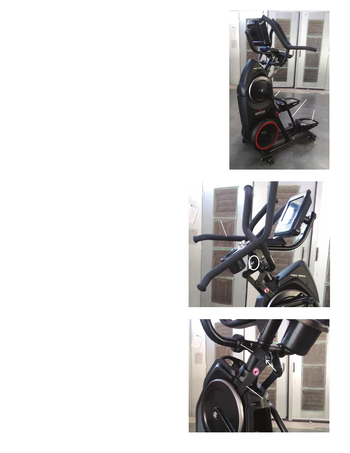
6. Place a rag or protective material below the Connector Arm to protect
the Shrouds from potential scratches from the Connector Arms.
7. Using a 6mm hex wrench, remove the hardware that connects the Con-
nector Arm and the Pivot Arm.
Note: The Connector Arm will pivot downward if not lowered slowly onto
the rag protecting the Shroud.
Left Upper
Handlebar
Pivot Arm
Connector Arm
Cap
Leg Assembly
Foot Pedal